- If equipped with a power sliding door, disable the PSD system by removing the PSD 15A fuse from the instrument panel (I/P) fuse block.
- Remove the tail lamp assembly. Refer to Tail Lamp Assembly and /or Backup, Sidemarker, Stop, Turn Signal Bulb Replacement.
- Disconnect the rear center roller bracket (4) from the door by removing the pin (1), slide the door with the center roller bracket all the way forward.
- Remove the cover (4) at the rear roller assembly (3) behind the tail lamp held on with one screw.
- Remove the cable from the rear roller to supply enough cable to remove the center roller bracket.
- Remove the sliding door center track cover. Refer to Rear Side Door Center Track Cover Replacement.
- Disconnect cables from the center roller bracket (3), remove the center roller bracket from the track.
- Start the tensioning procedure for the drive unit at this step.
- Reinstall the cable (1) to rear roller and guide (3). Be sure the rear cable is guided through the stop bracket.
- With tech standing at the center of the rear wheel, grab both cables (1, 2) and pull cables toward each other.
- Hold front cable extended and stationary and pull rear cable forward and hold.
- Rapidly release only the rear cable while maintaining tension and in the same position as noted for the front cable.
- Check for limp cables.
- Pull both cables again. The cables should now be able to pull past each other.
- If barrels do not overlap one inch after relieving tension, repeat steps 10 thru 14 until they overlap.
- Reinstall the cables (3) to the center roller bracket (1) and position the roller bracket into the track, while maintaining the tension on the rear cable by slightly pulling in outboard direction.
- Move the center roller bracket toward the front of the vehicle until the roller bracket stops in the track, while keeping tension on the rear cable (2) with the other hand.
- While keeping outward tension on the rear cable and holding down the center roller bracket (1) move the roller bracket rearward, and listen for an audible click to come from the clutch housing.
- Move the roller bracket forward near the corner of the track.
- Hold the roller bracket downward, pull the rear cable out from the inside track until you feel change in stiffness and release. The cable should snap quickly back into the track.
- Move the center roller bracket rearward toward the full open stop. Observe the rear cable. If the cable sags and droops out of the center track, the cable is not tensioned. Repeat steps 16 thru 20.
- Cable is properly tensioned when the cable has minimal sag during manual motion.
- Install the rear roller cover and screw.
- Install the sliding door center track cover. Refer to Rear Side Door Center Track Cover Replacement.
- Install the tail lamp assembly. Refer to Tail Lamp Assembly and /or Backup, Sidemarker, Stop, Turn Signal Bulb Replacement.
- Install the door center roller bracket (2) to the body roller bracket (4) by installing the pin (1).
- Close and latch the door manually.
- If equipped with a power sliding door, enable the PSD system by installing the PSD 15A fuse into the I/P fuse block.
- Operate the door and verify the adjustment.
Important: By removing the power sliding door (PSD) 15A fuse, the low current logic power for both the LH and RH power sliding door modules (PSDM) will be interrupted and both PSDs will be inoperative.
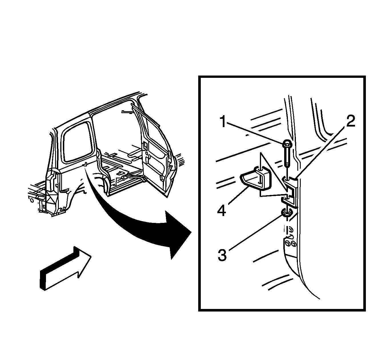
Important: It will be necessary to use a floor jack or a similar support to keep the door level when the rear center roller bracket is being removed.
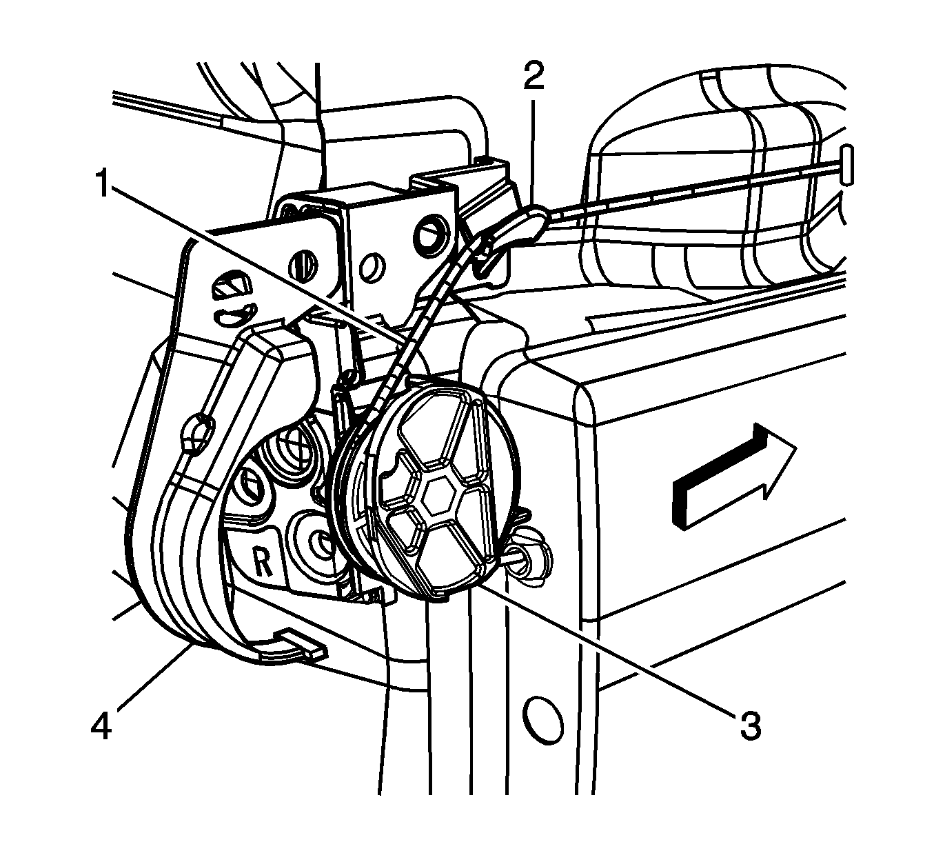
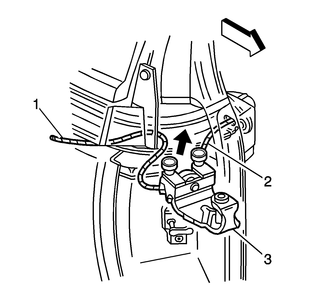
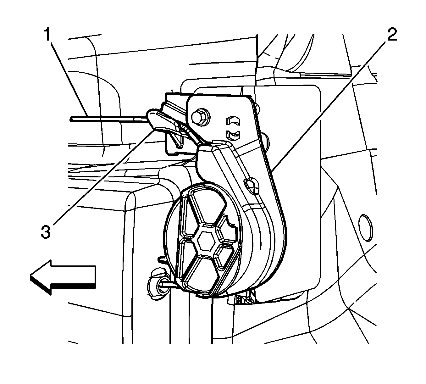
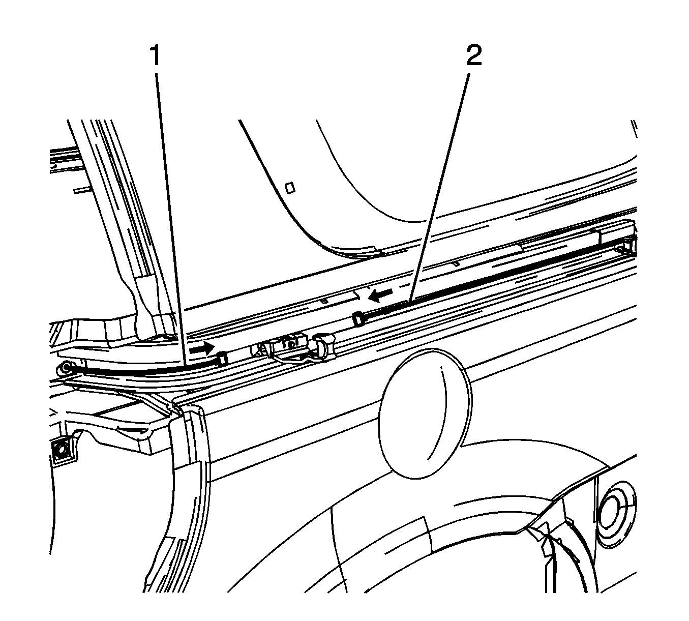
Important: Note the barrels on the end of the cables will not pull past each other, 25.4 mm (1 in) apart.
If the cable ends pull past each other skip step 10 thru 13 and go to step 14.Important: Note: The cable must be release in a fast motion when doing this step.
Slowly release cables. The barrels at the end of the cables should be overlapping 25.4 mm (1 in).
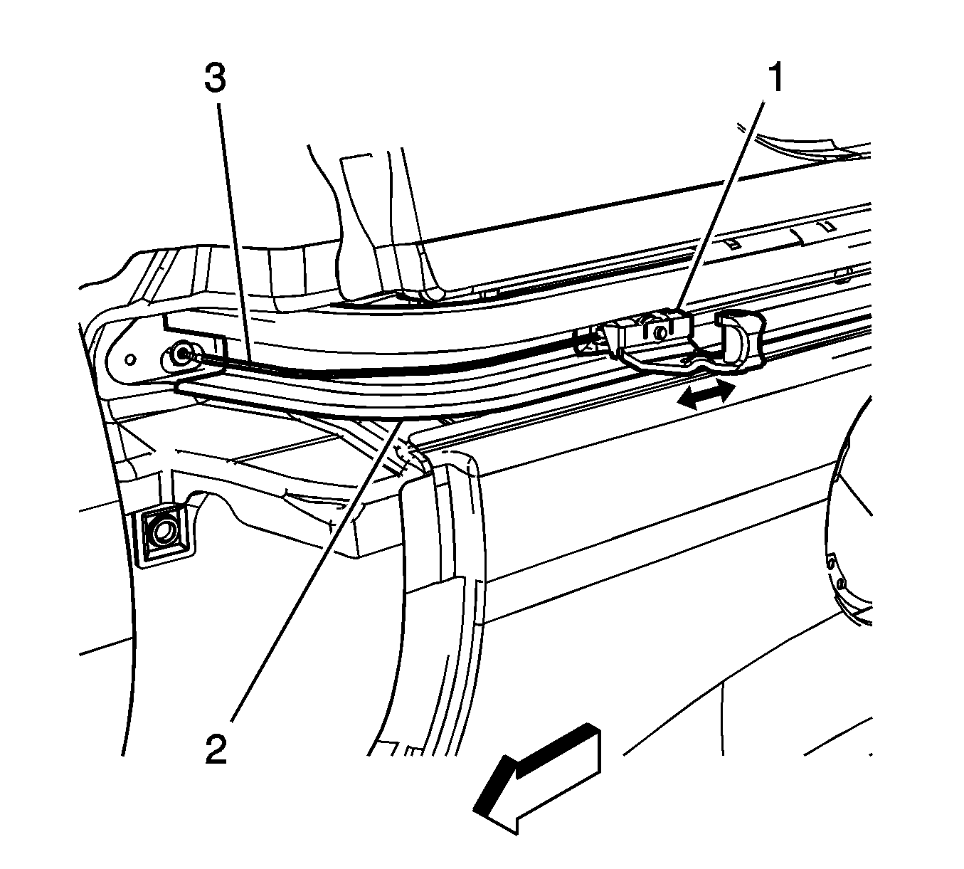
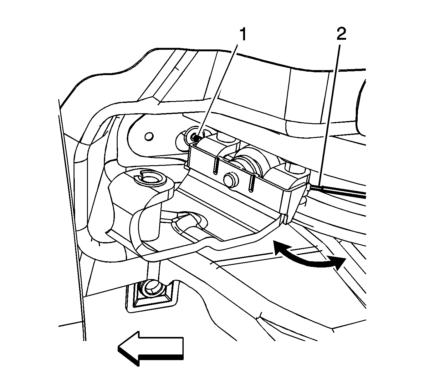

Important: Tension must be kept on rear cable.
Continue to move roller bracket rearward, in one motion, release the rear cable and finish pushing roller bracket into the track bumper. The cable has to spring inside the center track.
Notice: Refer to Fastener Notice in the Preface section.
Tighten
Tighten the screw to 9 N·m (80 lb in).

Important: By installing the 15A fuse, the low current logic power will be restored to both the LH and RH PSDMs and the PSDs will be operational. However, both PSDMs will have to learn the full open and full closed positions of the PSD. Refer to Rear Side Door Actuator Control Module Programming and Setup.
