Tyco/AMP Connectors CM 42-Way
Special Tools
J-38125 Terminal Repair Kit
Removal Procedure
- Locate the connector position assurance (CPA) on the connector body and pull the CPA out. The CPA is on the wire harness side of connector.
- Disconnect the connector from the component.
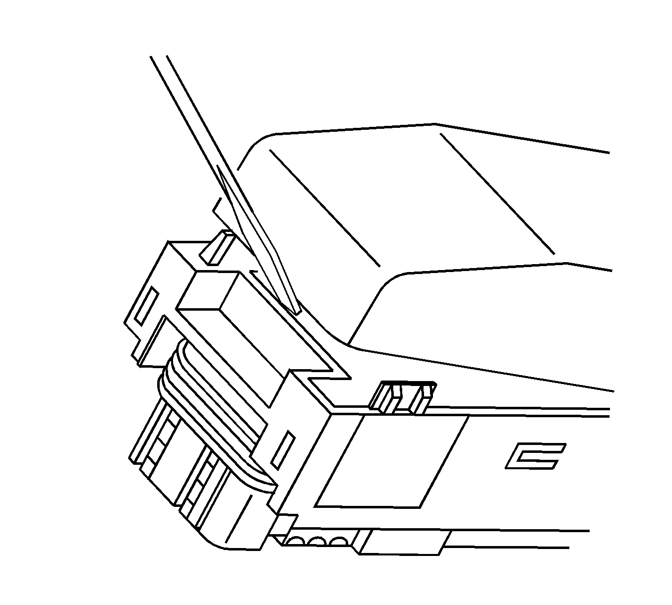
- Use a small flat-bladed tool to gently pry off the dress cover by inserting the tool under the cover opposite the harness side and prying up.
- Remove the cover.
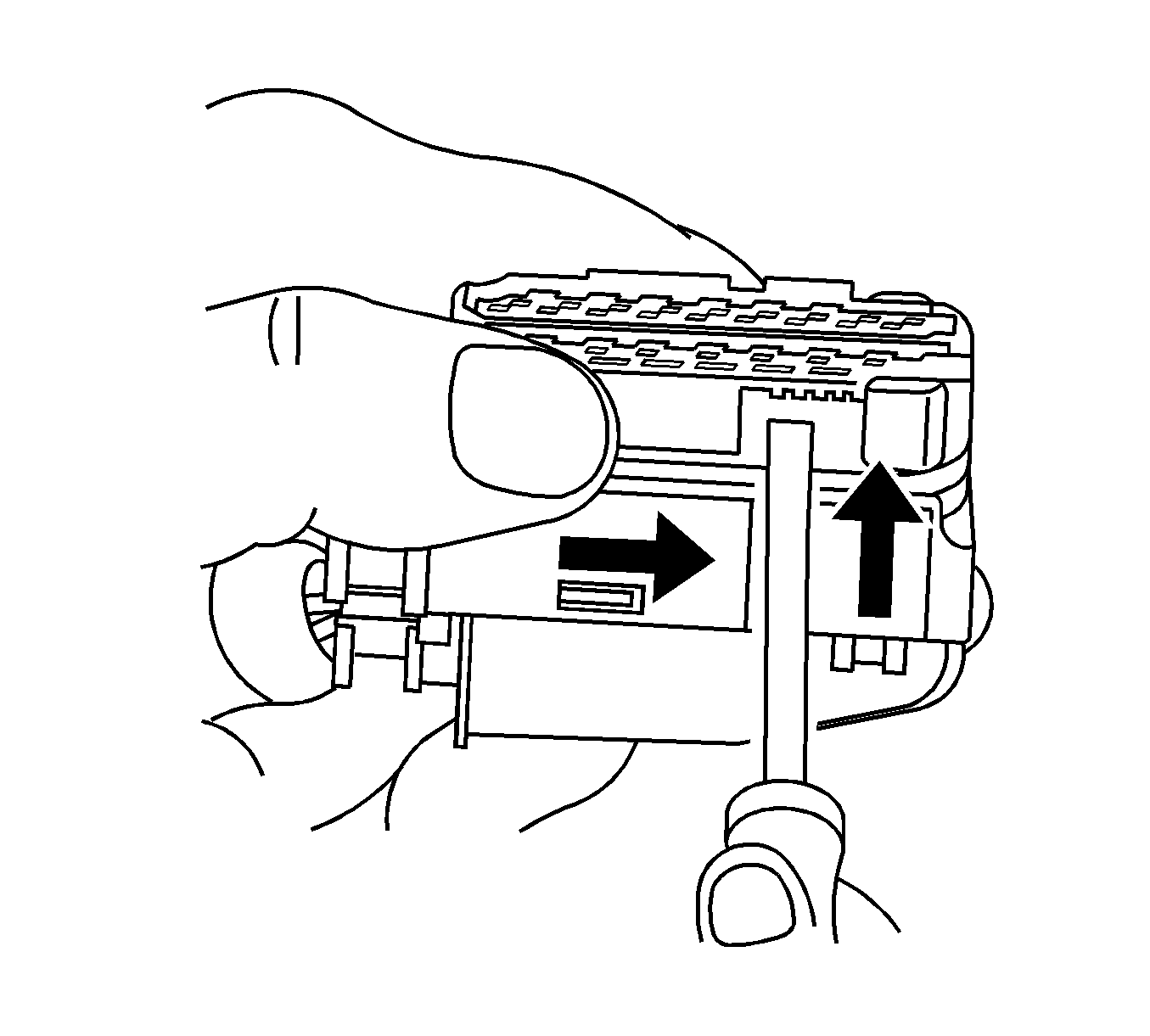
- Using a small flat-bladed tool, push on the side of the nose piece retainer while pushing the nose piece forward with your thumb. This will release the terminal position assurance (TPA).
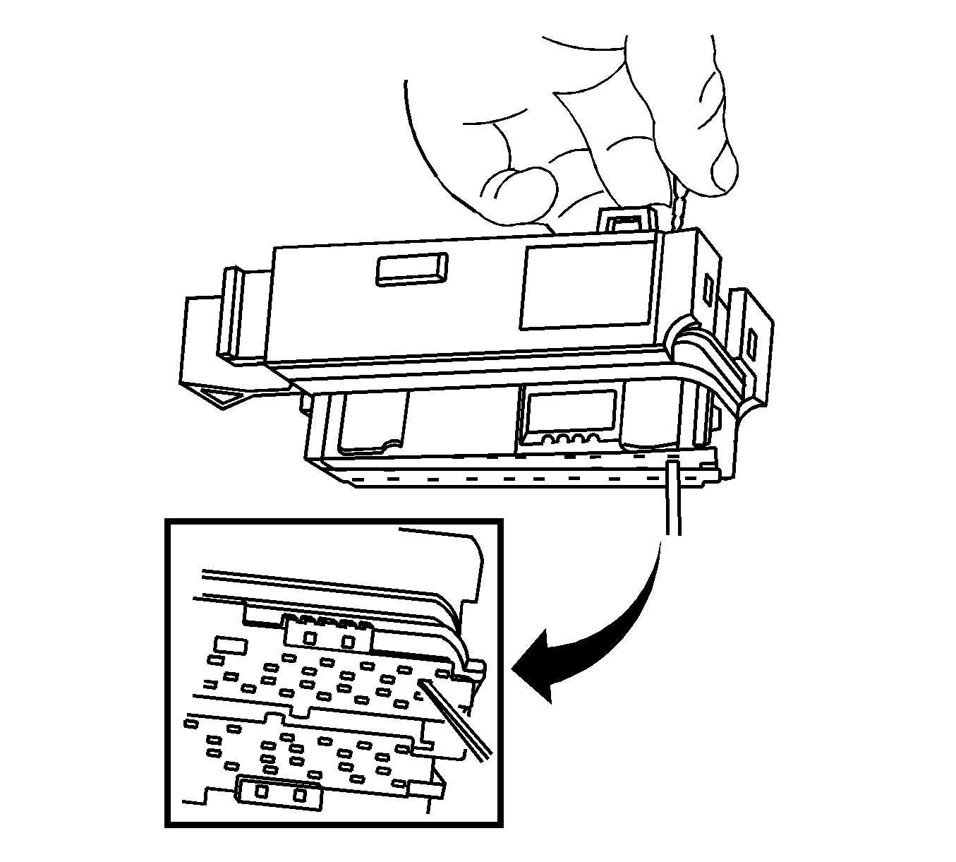
- Insert the J 38125-12A into the corresponding terminal release cavity. The release cavities are the 2 center rows of cavities on one half of the connector.
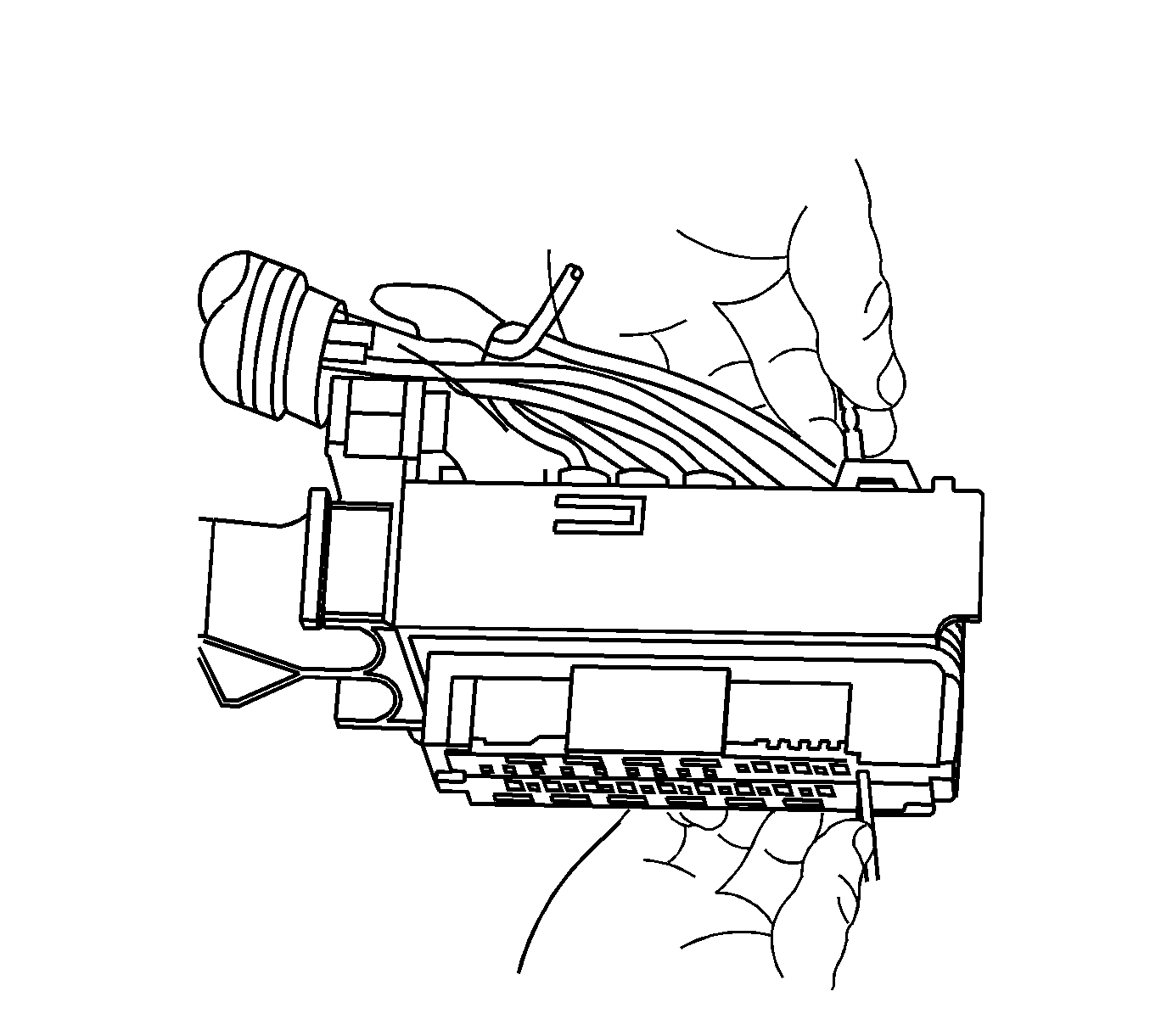
- Pressing the J 38125-12A tool in the release cavity of the terminal you are removing, gently pull the wire out of the back of the connector. Always remember never use force when pulling a terminal out of a connector. See the release tool cross reference in the Reference Guide of the J-38125 to ensure that the correct release tool is used.
Terminal Repair Procedure
Use the appropriate terminal and crimper in the J-38125 in order to replace the terminal.
Tyco/AMP Connectors Sensor
Special Tools
J-38125 Terminal Repair Kit
Terminal Removal Procedure
- Disconnect the connector from the component.
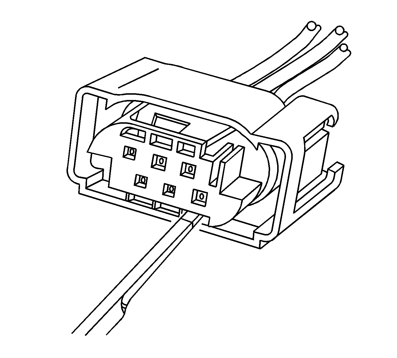
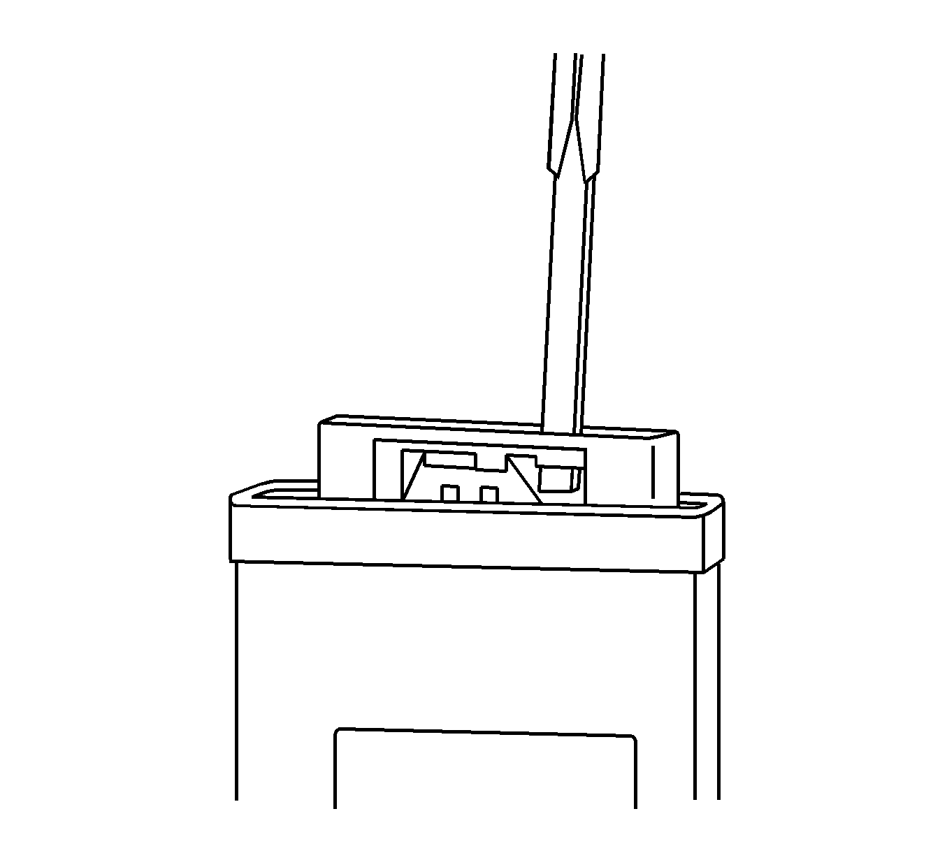
- Insert the J 38125-11A tool into the cavity on the lower right hand face of the connector until the terminal release tang access panel slides over.
- Ensure that the terminal release tang access panel is in the correct location to access the terminals.
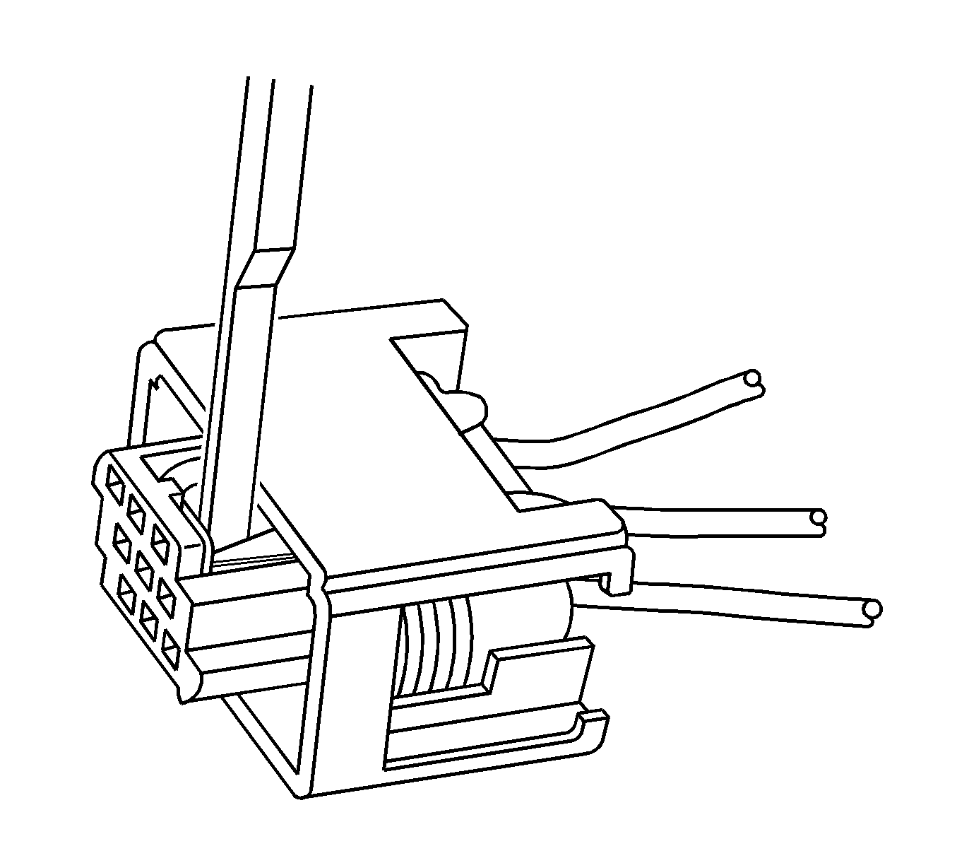
- Push the wire side of the terminal that is being removed toward the connector and hold it in position.
- Insert the J 38125-11A into the terminal release tang access slot located behind the access panel of the connector and press down on the terminal while carefully pulling the terminal out of the connector. Always remember never use force when pulling a terminal out of a connector. If the terminal is difficult to remove, repeat the entire procedure.
Terminal Repair Procedure
Use the appropriate terminal and follow the instructions in the J-38125 .
Tyco/AMP Connectors 0.25 Cap
Special Tools
J-38125 Terminal Repair Kit
Terminal Removal Procedure
- Disconnect the connector from the component by pressing down on the connector position assurance (CPA).
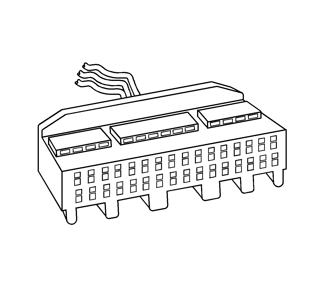
- Use a small flat-bladed tool to release the terminal position assurance (TPA) by inserting the tool in the small recess on the side of the connector and pushing up until the TPA releases from the connector body. The TPA should raise just slightly. Do not try to remove the TPA.
- Repeat the process for the other side of the connector.
- Ensure that the TPA is in the proper position to remove the terminals.
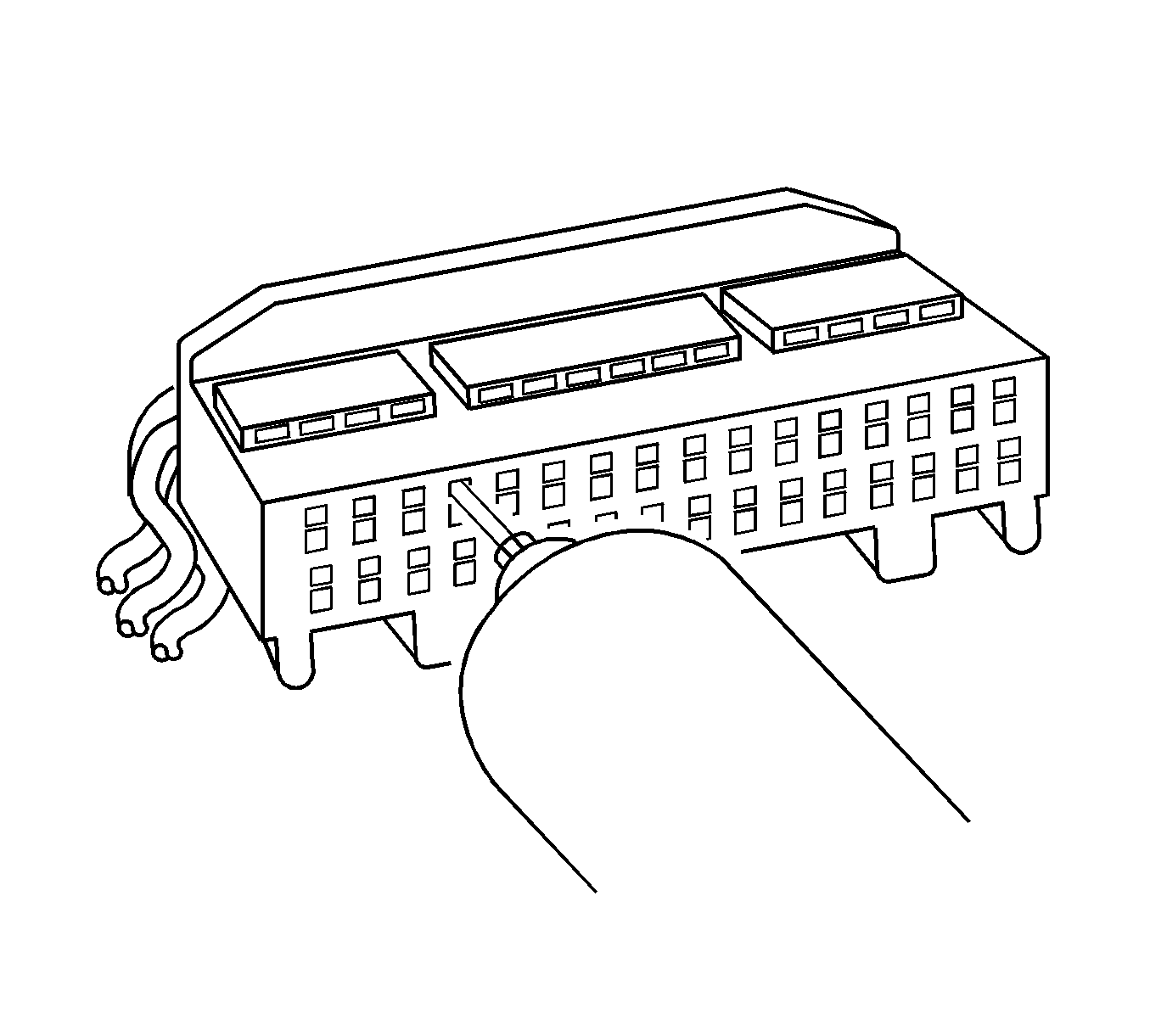
- While pushing the terminal forward, insert the J 38125-24 in the release cavity above the terminal you are removing, gently pull the wire out of the back of the connector. Always remember never use force when pulling a terminal out of a connector. See the release tool cross reference in the Reference Guide of the J-38125 to ensure that the correct release tool is used.
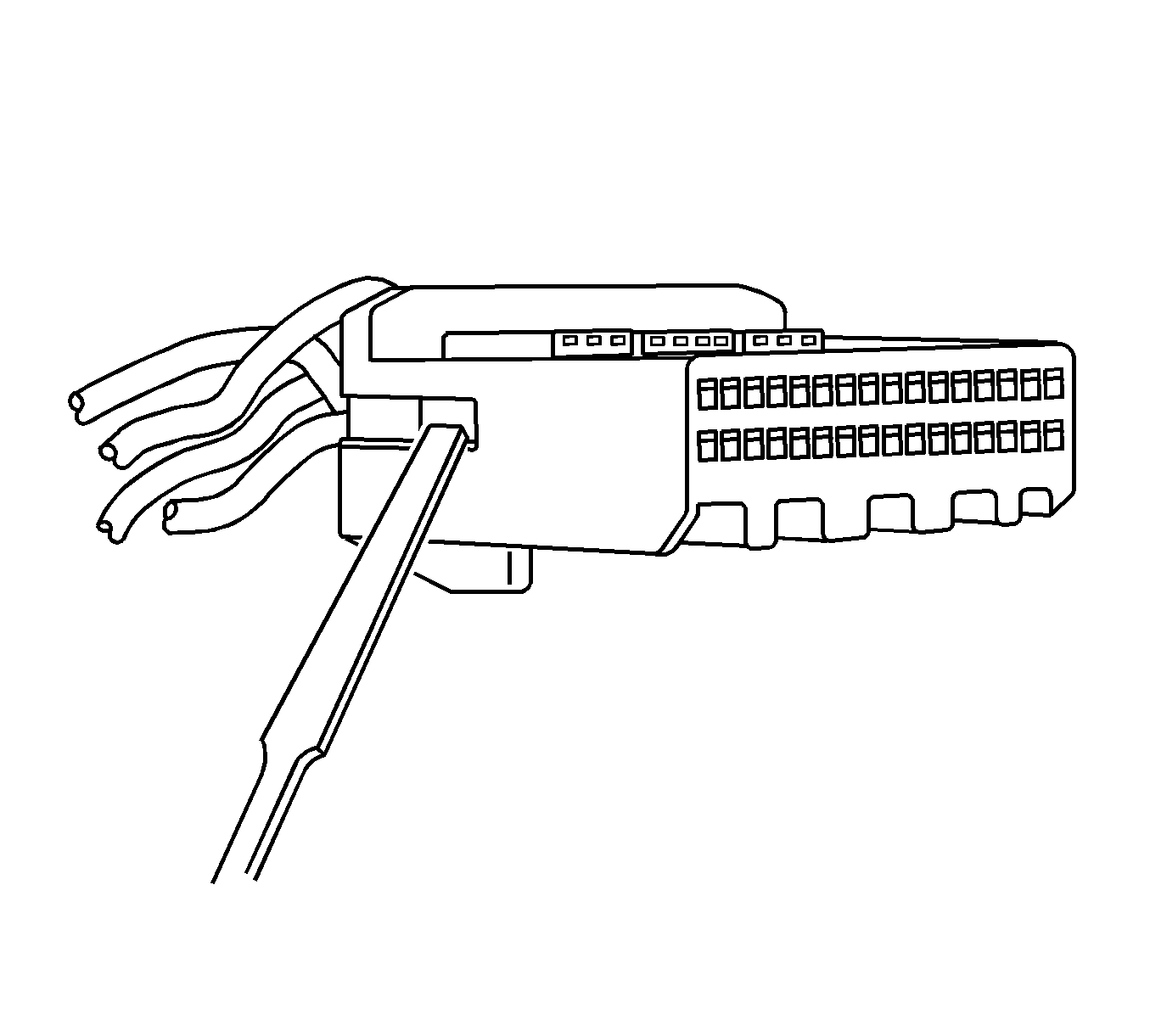
Note: The TPA on this connector cannot be removed unless the terminals are removed first. The TPA will come out of the connector body, but only slightly. When the TPA is slightly raised the terminals can be removed. Using excessive force to remove the TPA with the terminals still in the connector will damage the connector.
Terminal Repair Procedure
Use the appropriate terminal and follow the instructions in the J-38125 in order to replace the terminal.
Tyco/AMP Connectors 43-Way
Special Tools
J-38125 Terminal Repair Kit
Removal Procedure
Follow the steps below in order to remove terminals from the connector.
- Locate the lever lock on the wire dress cover. Slide the lever lock away from the connector body.
- Disconnect the connector from the component.
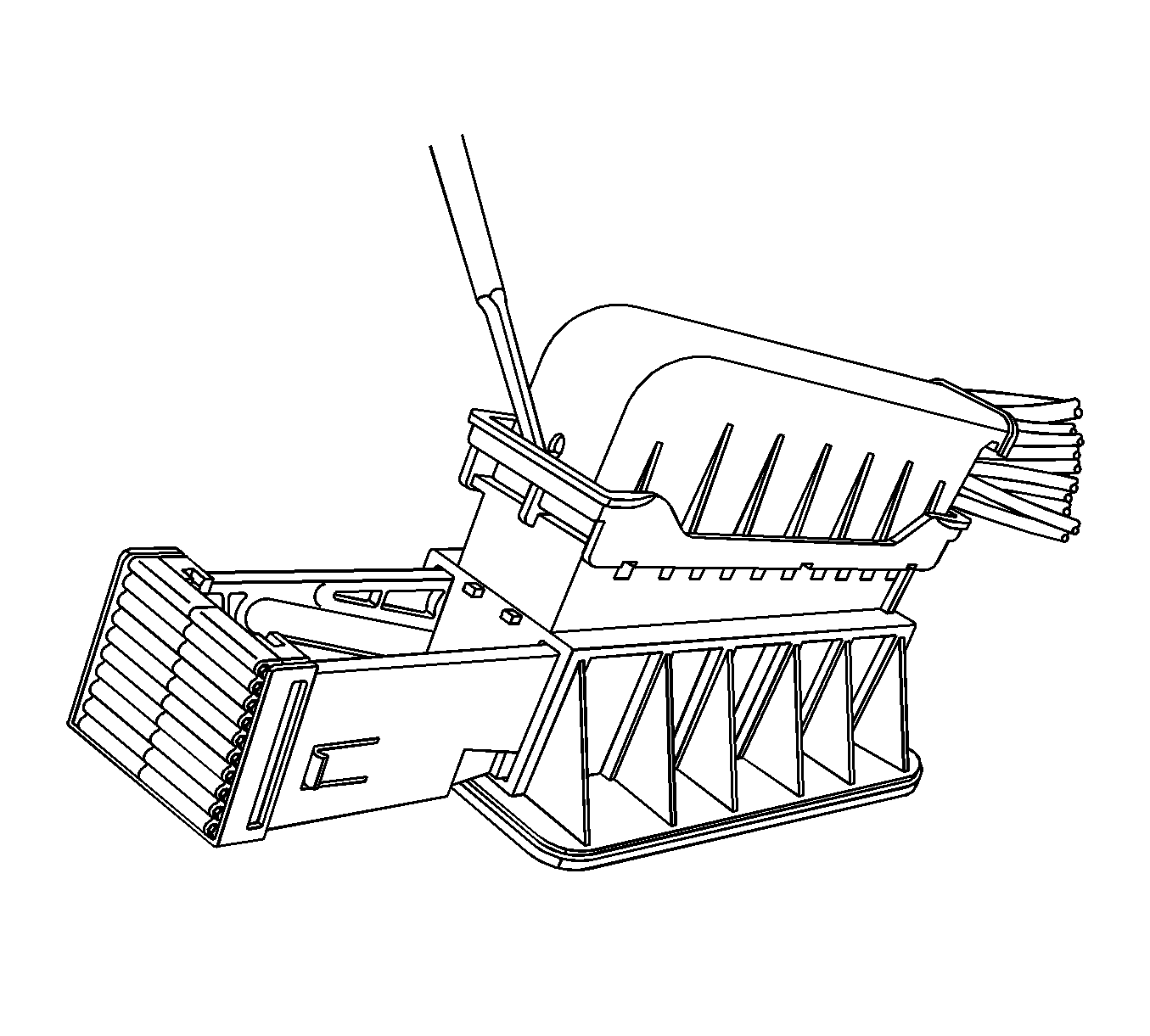
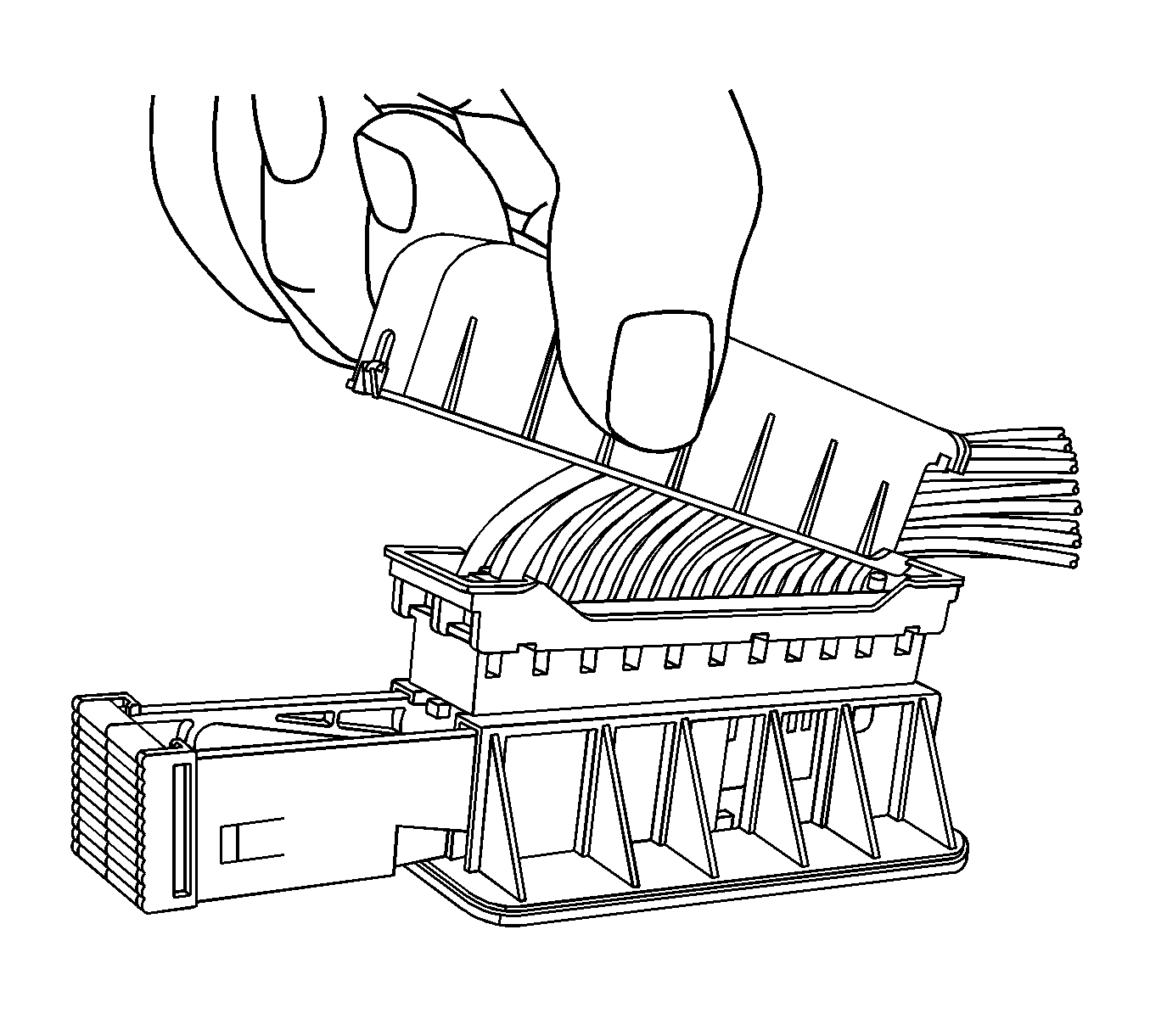
- Locate the dress cover locking tabs on the dress cover of the connector. Using a small flat-blade tool release all of the locking tabs.
- Once the locks are unlocked, lift the dress cover off.
- Release the TPA by inserting a small flat-blade tool into the blue locking tabs on both ends of the connector. Gently slide the TPA up to the released position on both ends.
- For the larger terminals insert the J 38125-13A tool to release the terminals by inserting the tool into the terminal release cavity. For the smaller terminals insert the J 38125-12A tool to release the terminals by inserting the tool into the terminal release cavity. See the release tool cross reference in the Reference Guide of the J-38125 to ensure that the correct release tool is used.
- View of the release tool being used for the larger terminals.
- View of the release tool being used for the larger terminals.
- View of the release tool being used for the smaller terminals.
- While holding the removal tool in place, gently pull the wire out of the back of the connector. Always remember never use force when pulling a terminal out of a connector.
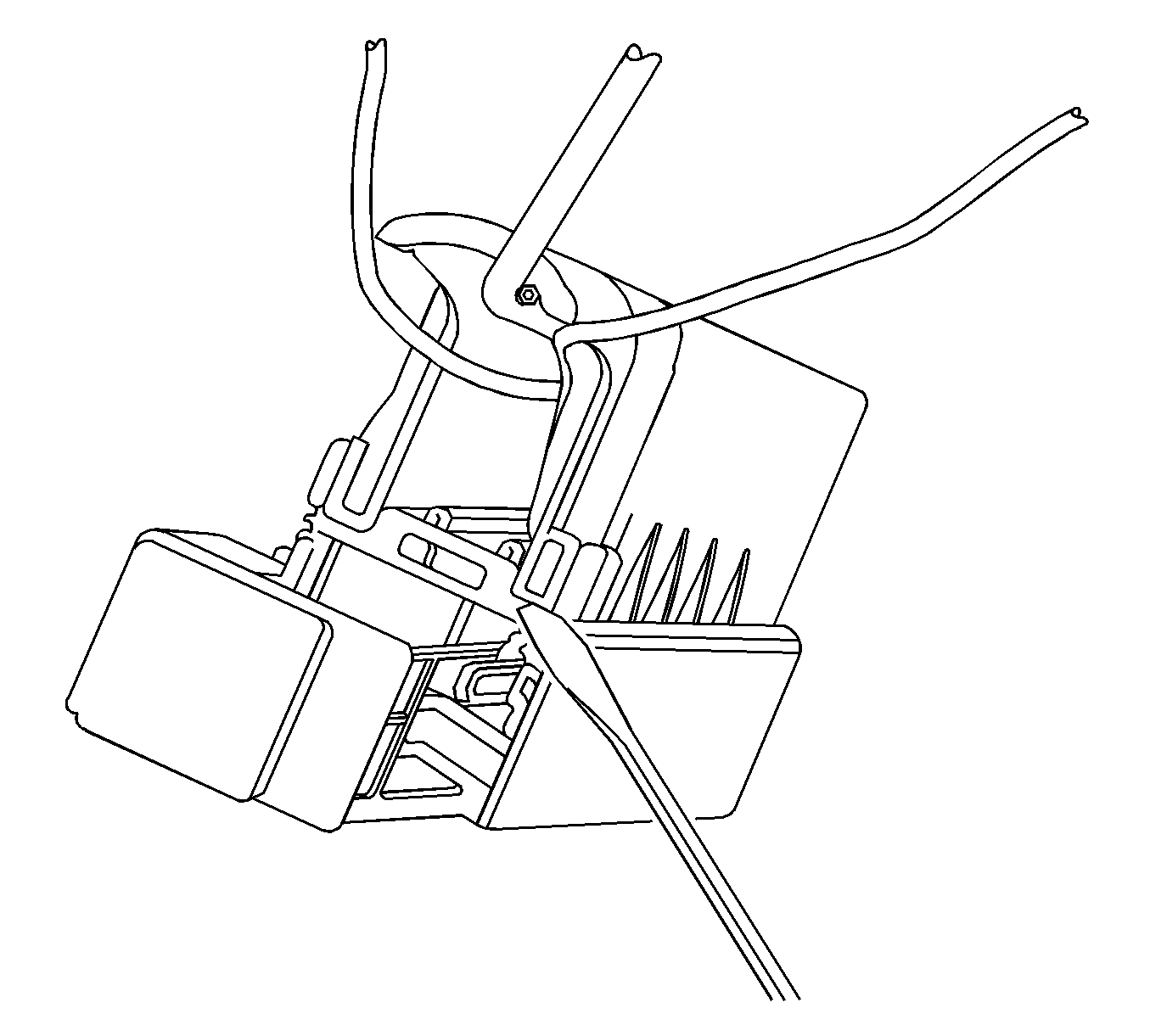
Note: Always use care when removing a terminal position assurance (TPA) in order to avoid damaging it.
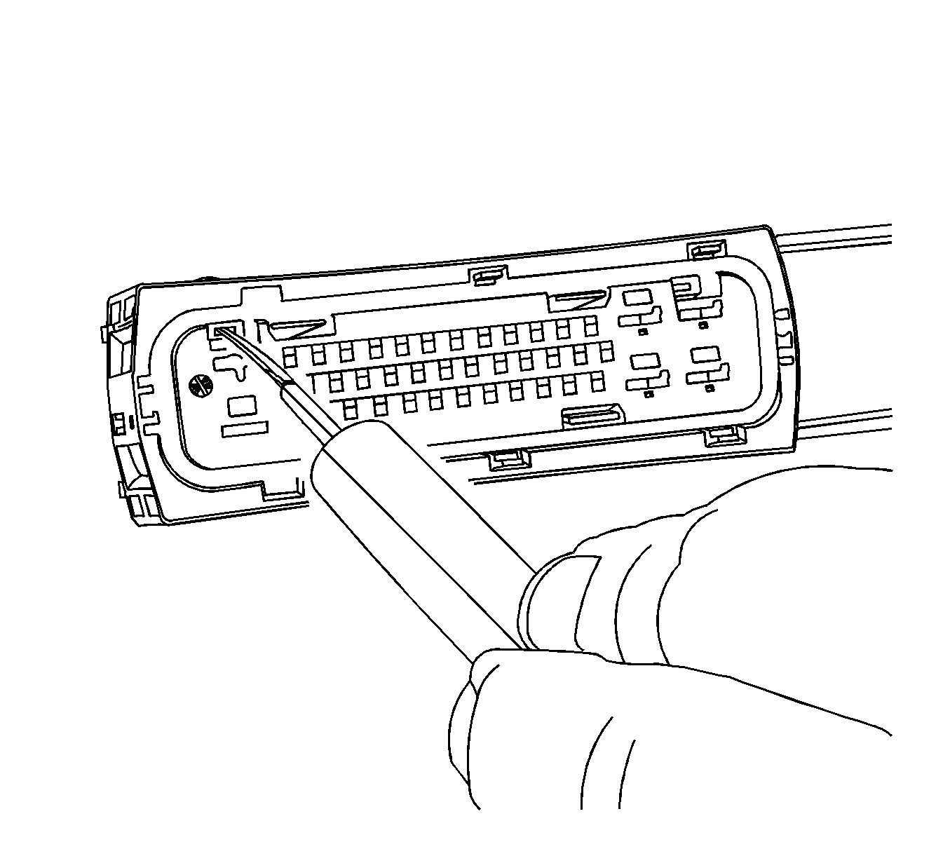
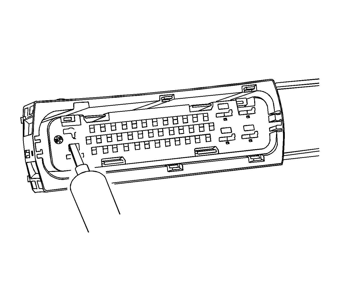
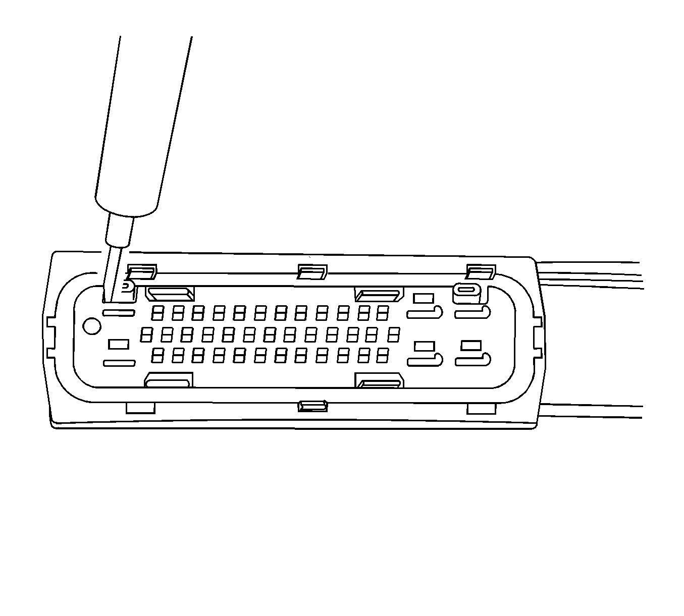
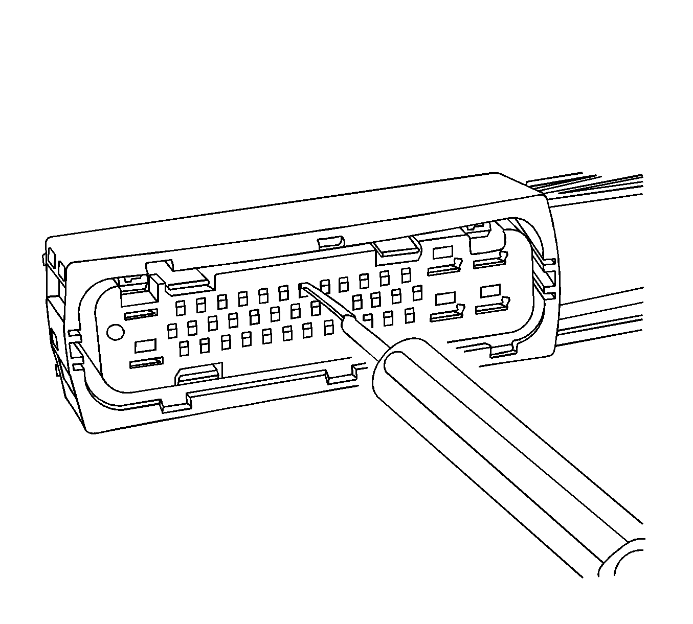
Repair Procedure
Use the appropriate terminal and follow the instructions in the J-38125 .
Location of the terminal in the repair tray and the proper crimp tool can be found in the appropriate connector end view.
Tyco/AMP Connectors Door Module
Special Tools
J-38125 Terminal Repair Kit
Removal Procedure
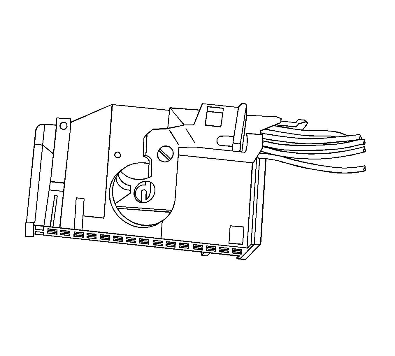
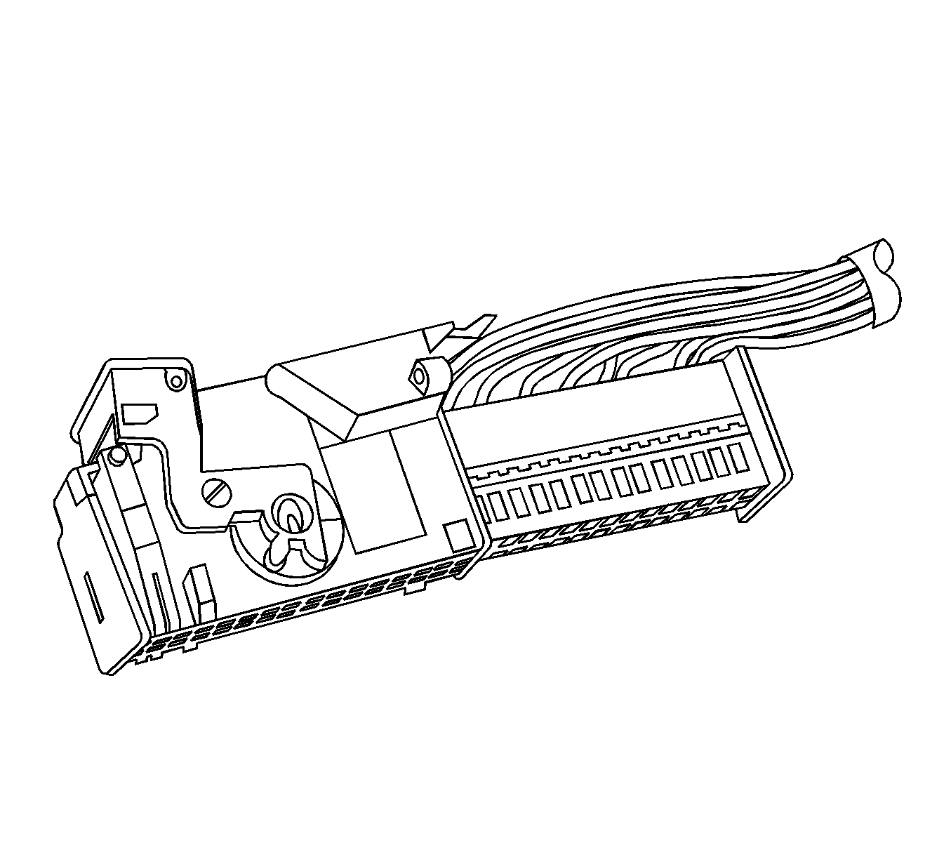
Side view of connector.
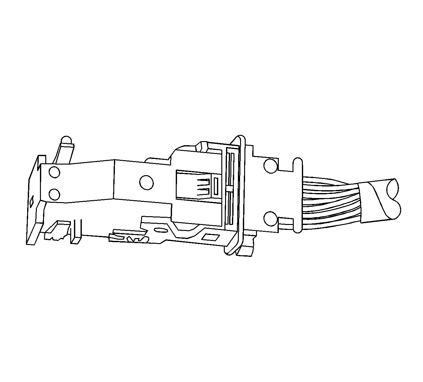
View of top of connector.
- Locate the assist lever and lock on the top of the connector.
- While depressing the lock, pull the lever over and past the lock.
- Disconnect the connector from the component.
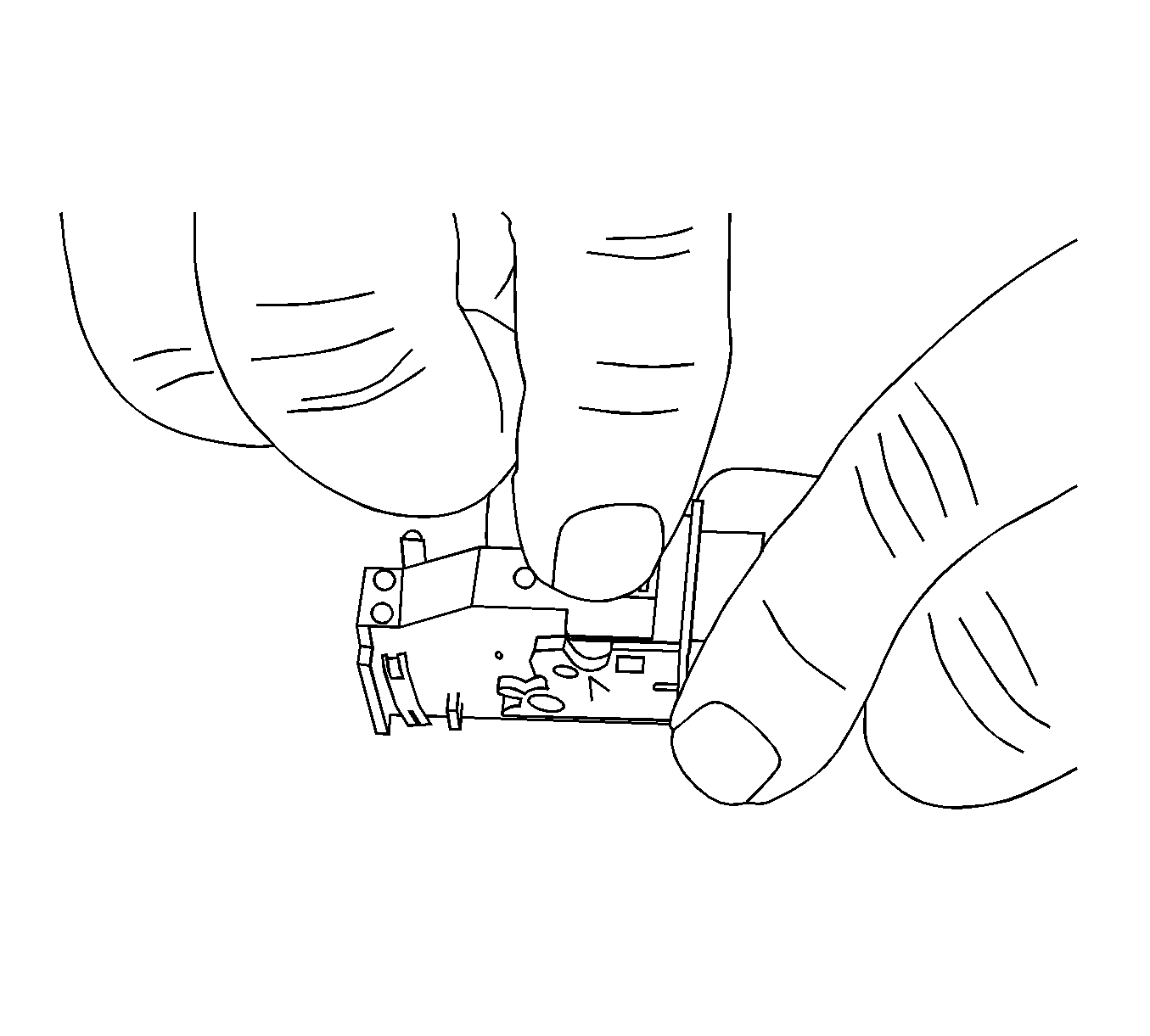
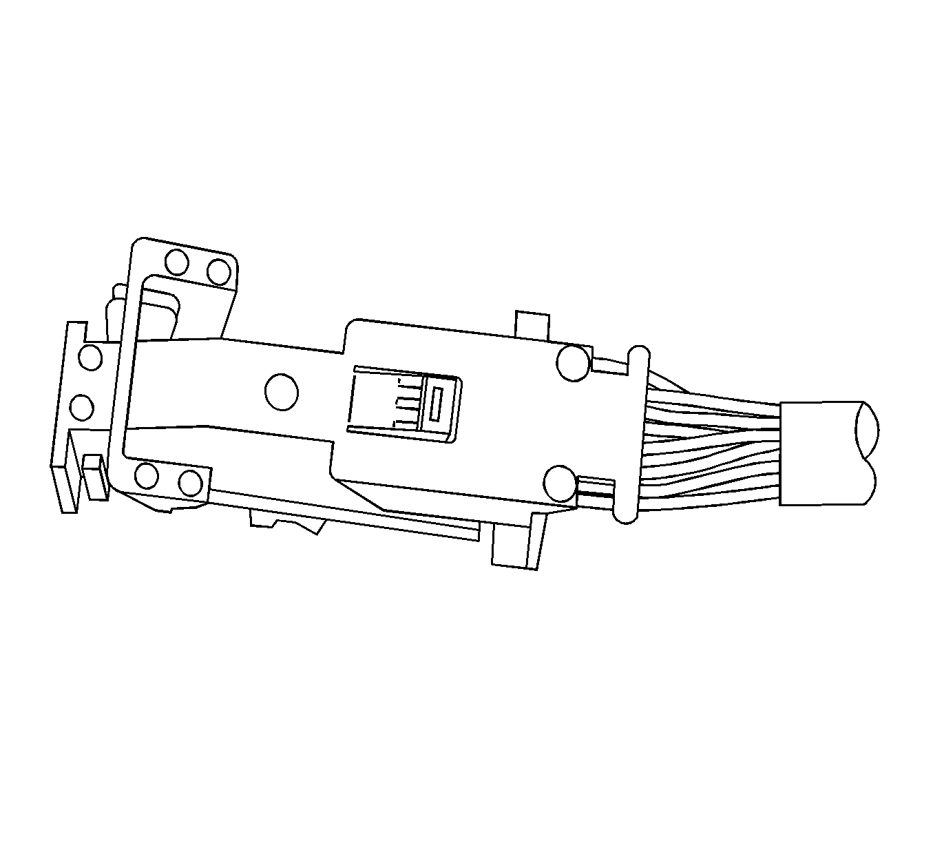
- Locate the dress cover locking tabs at the rear of the connector. Use a small flat-blade tool to release the locking tabs. Repeat this procedure for the other locking tab.
- Once the locking tabs are unlocked, slide the inner connector out of the rear of the connector housing.
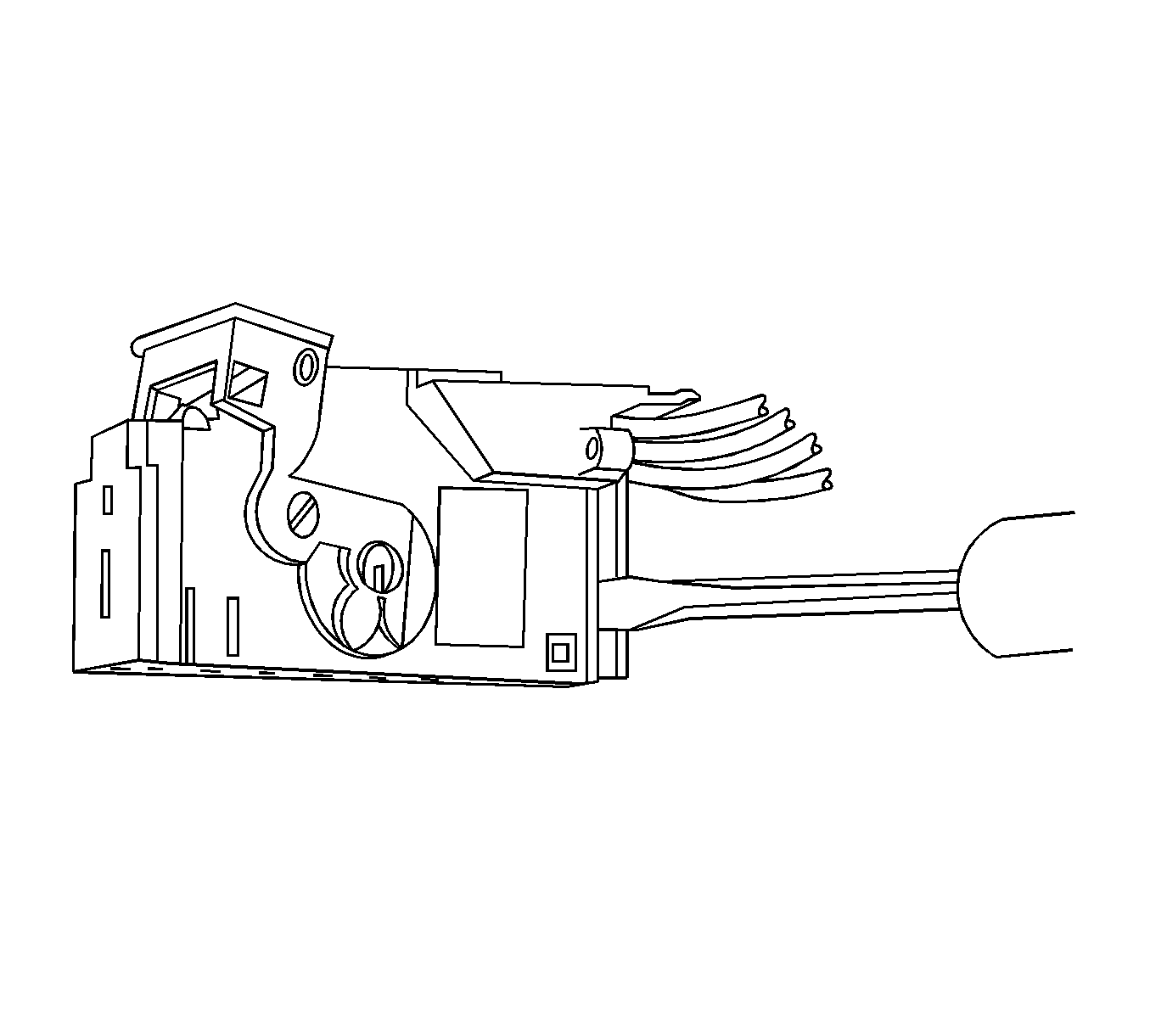
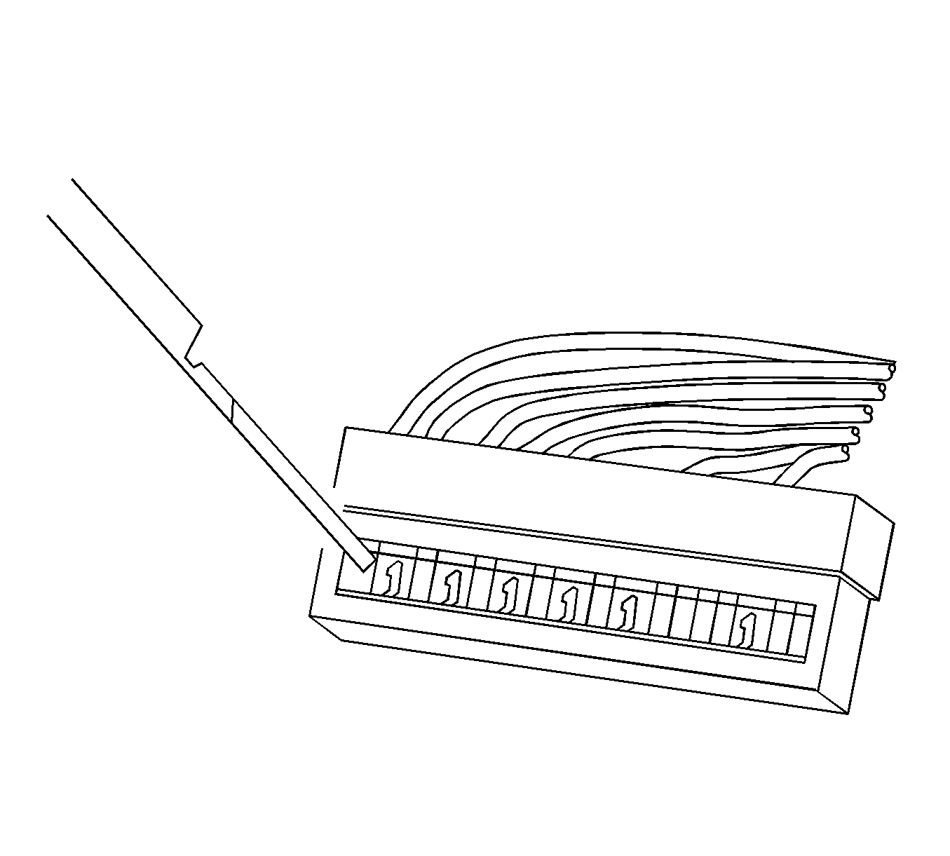
- Use the J 38125-12A tool to release the terminals by pressing on the tang. See the release tool cross reference in the Reference Guide of the J-38125 to ensure that the correct release tool is used.
- While holding the removal tool in place, gently pull the wire out of the back of the connector. Always remember never use force when pulling a terminal out of a connector.
Repair Procedure
Use the appropriate terminal and follow the instructions in the J-38125 .
Location of the terminal in the repair tray and the proper crimp tool can be found in the appropriate connector end view.
Tyco/AMP Connectors 102-Way Inline
Special Tools
J-38125 Terminal Repair Kit
Removal Procedure
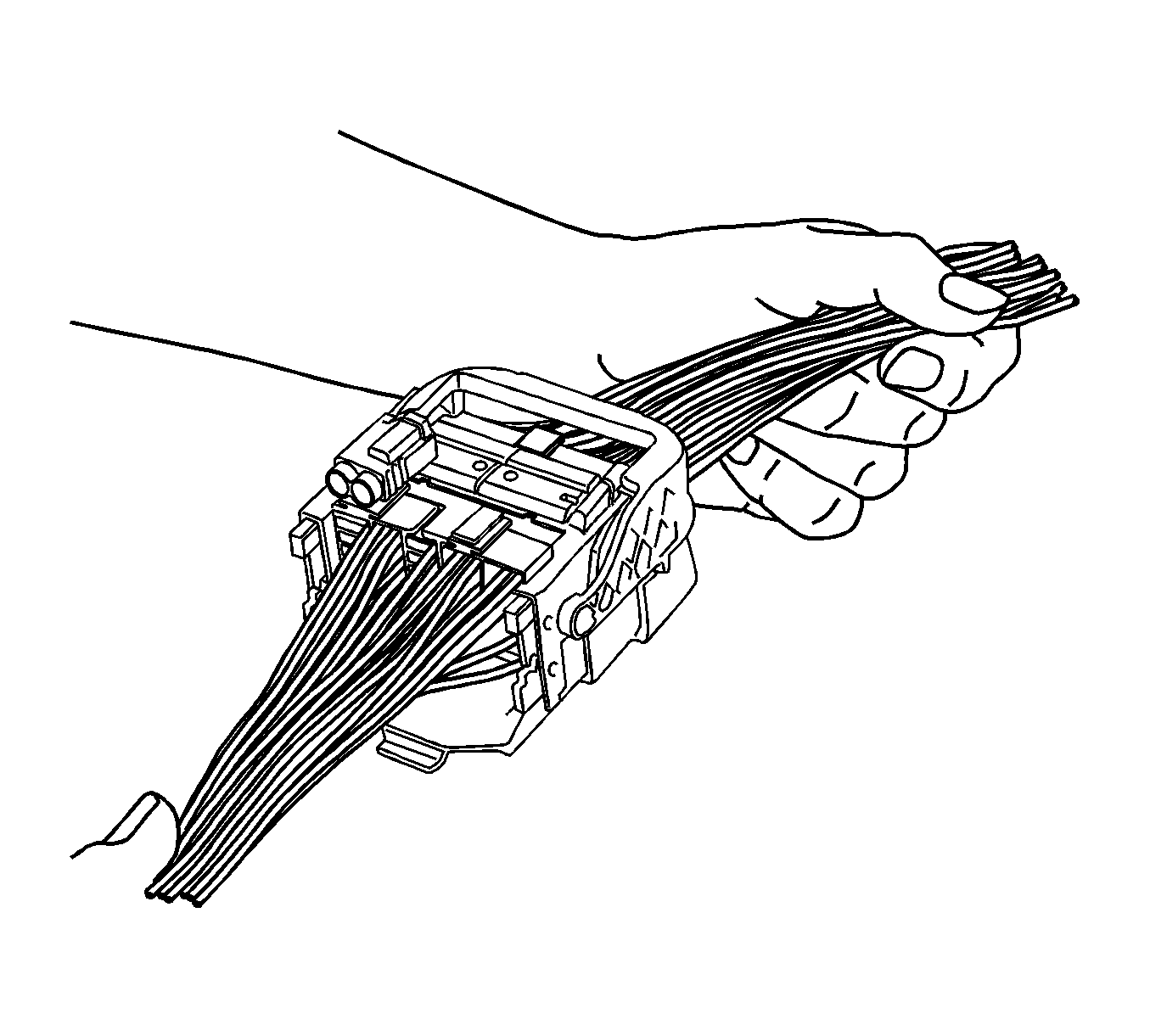
View of a typical connector in the assembled position.
- Pull the locking lever to the 90 degree position from the connector body.
- With the locking lever in the 90 degree position and the male connector body separated, it can be slid outward for removal.
- Slide the male connector body out away from the guide plates.
- Using terminal release tool J 38125-11A or equivalent, remove the TPA from the connector body.
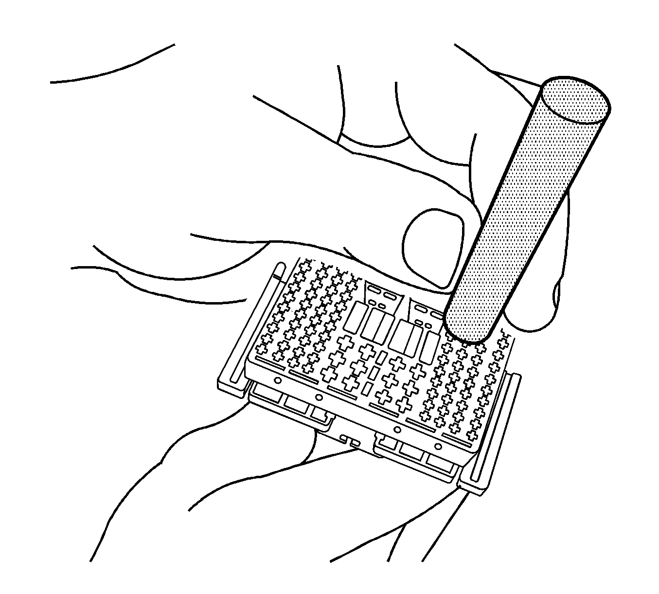
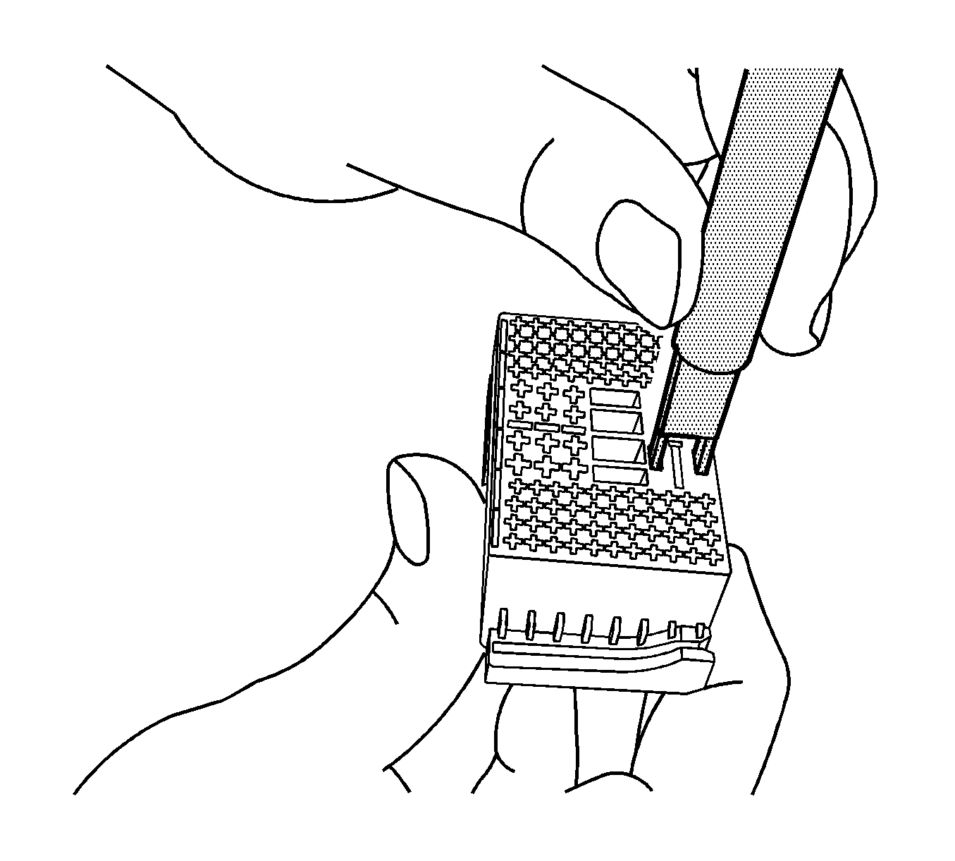
- Using terminal release tool J 38125-566, press the prongs into the holes on each side of the terminal to be removed to release the lock tabs and pull the terminal out of the connector body.
- Using terminal release tool J 38125-560, press the prongs into the holes on each side of the terminal to be removed to release the lock tabs and pull the terminal out of the connector body.
- Using terminal release tool J 38125-221, press the prongs into the holes on each side of the terminal to be removed to release the lock tabs and pull the terminal out of the connector body.
- The female connector body may have an additional connector hooked to the edge of the body. Use terminal release tool J-38125-11A or equivalent to release the locking tab and slide the connector off the female body.
- Move the locking lever 180 degrees from the connected position.
- With the locking lever in the 180 degree position the guide plates can be removed from the connector body.
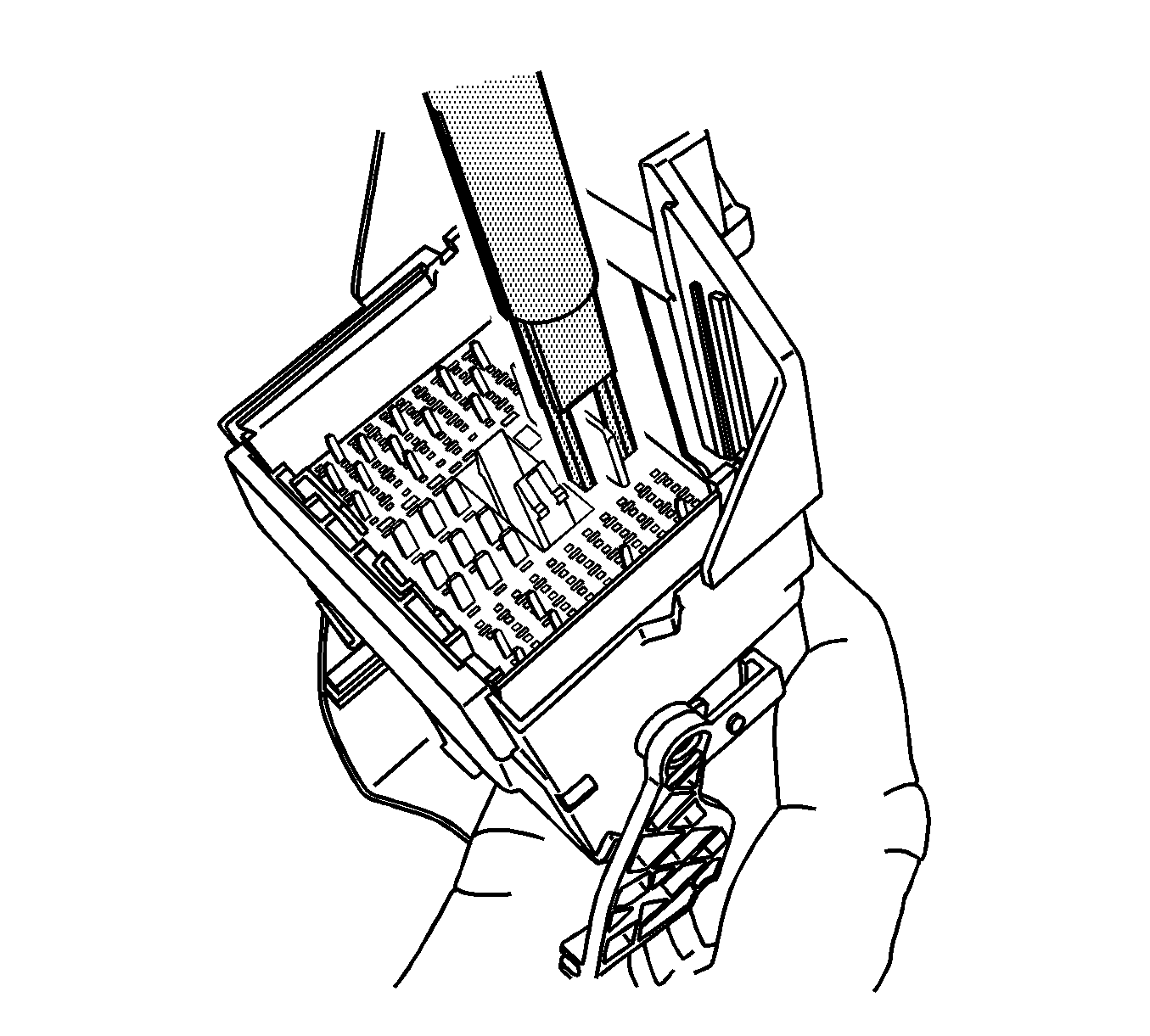
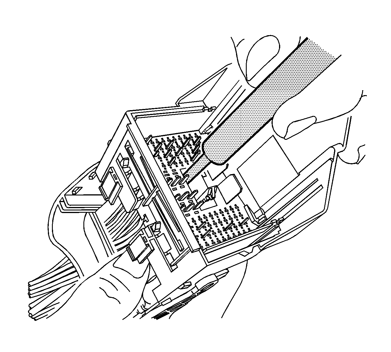
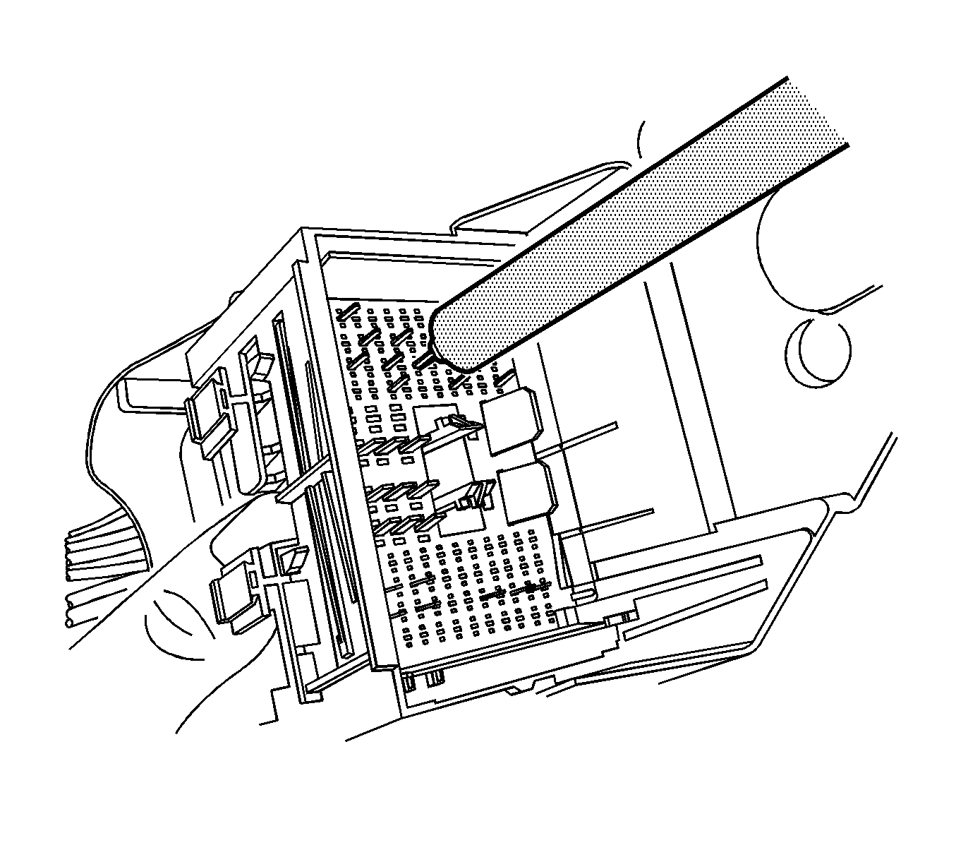
- Using terminal release tool J 38125-11A or equivalent, remove the TPA from the connector body.
- Using terminal release tool J 38125-216, lift the terminal plate past the terminals and out of the connector body cavity.
- Terminal plate will bind slightly on each corner.
- Using terminal release tool J 38125-221, press the prongs into the holes on each side of the terminal to be removed to release the lock tabs and pull the terminal out of the connector body.
- Using terminal release tool J 38125-212, press the prongs into the holes on each side of the terminal to be removed to release the lock tabs and pull the terminal out of the connector body.
- Using terminal release tool J 38125-560, press the prongs into the holes on each side of the terminal to be removed to release the lock tabs and pull the terminal out of the connector body.
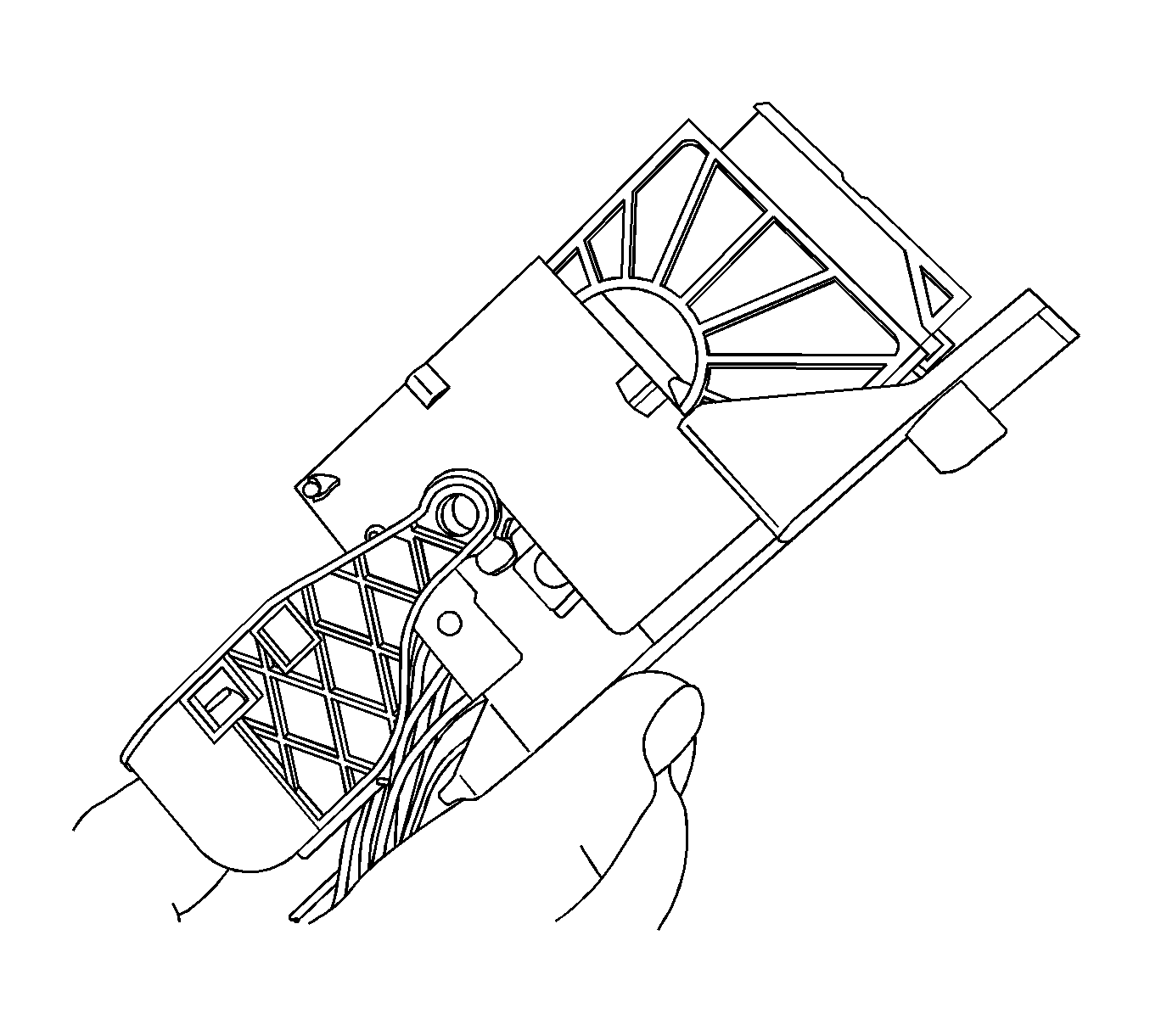
- Press the terminal plate back into the female connector to the preset position. The plate will bind slightly on each corner.
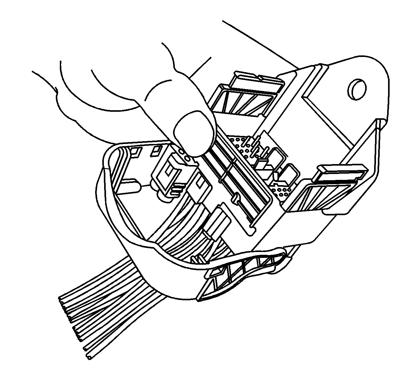
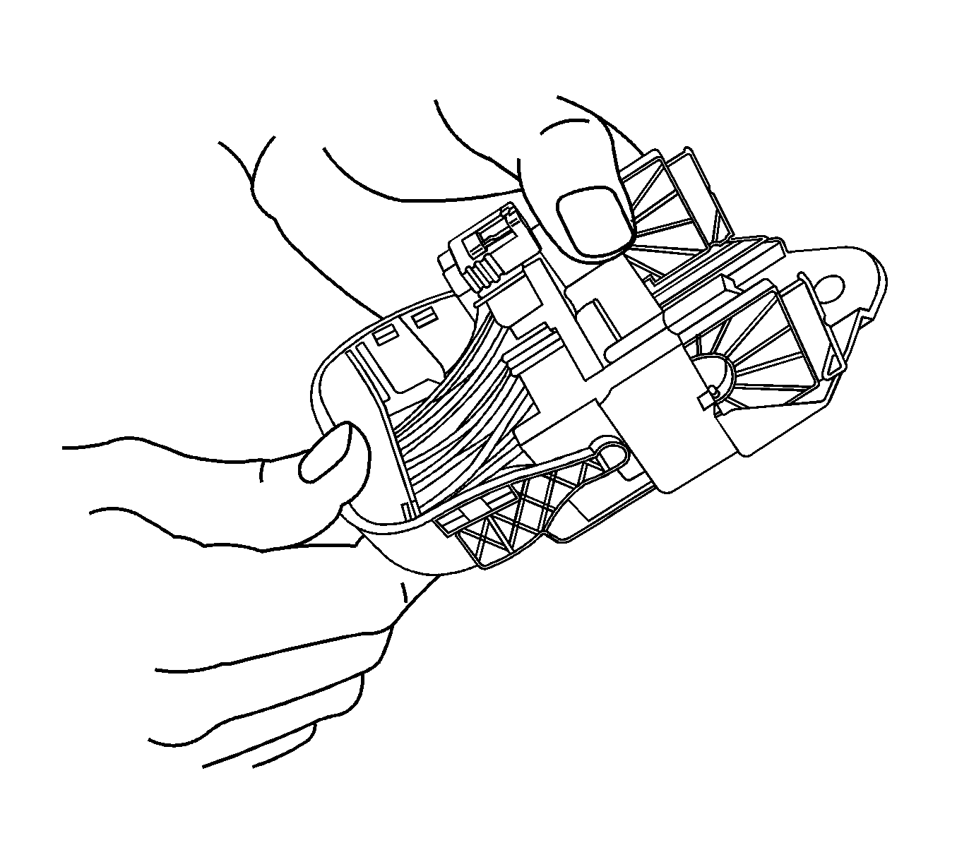
- With the locking lever in the 180 degree position, align the guide plates to mesh with the gears on the locking lever.
- Slide the male connector body back inward toward the guide plates.
- With the locking lever in the 90 degree position and the male connector body connected, it can be slid inward for assembly.
- Move the lever into the locked position or in the assembled position. This will pull the male connector down into the female connector.
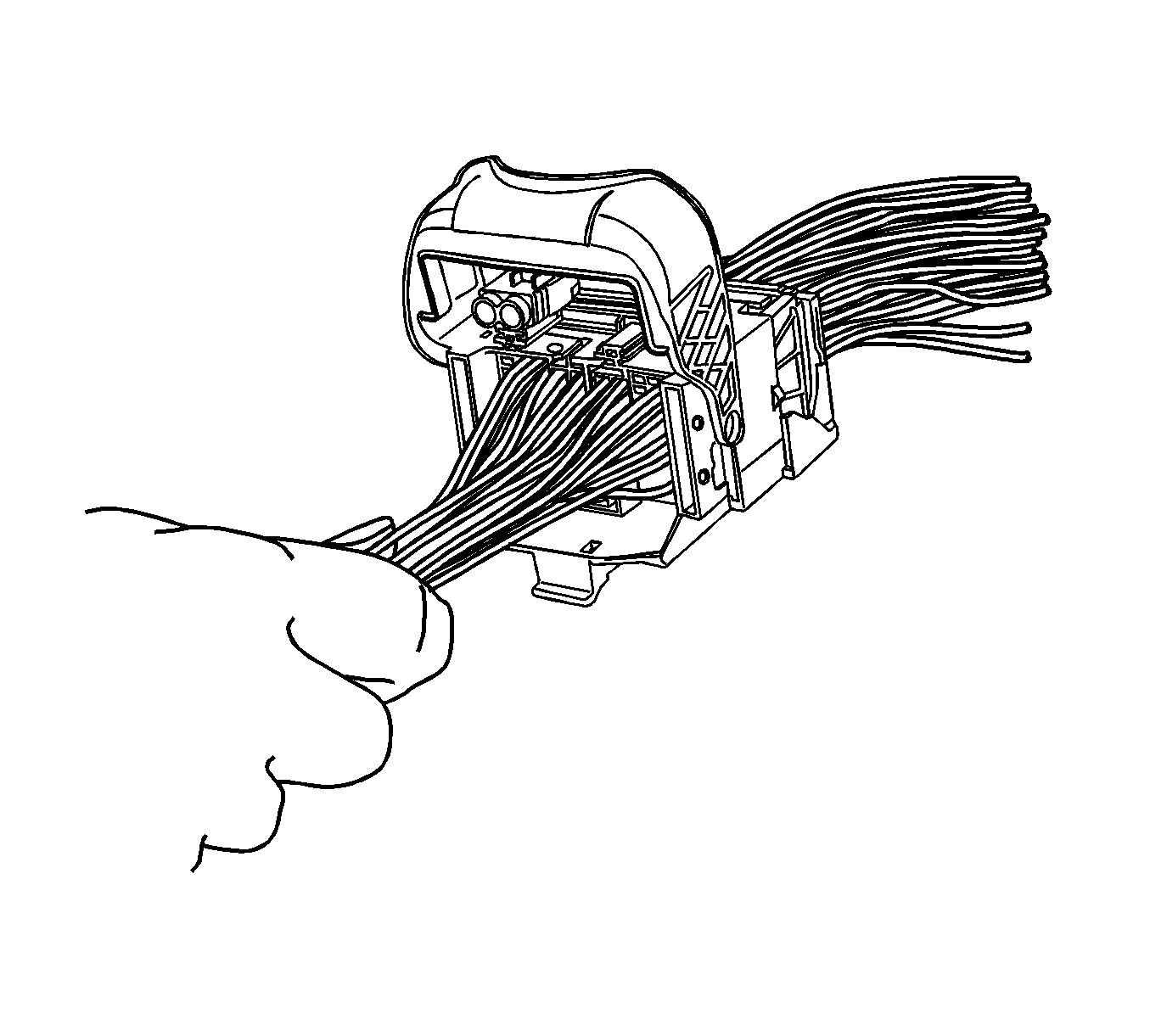
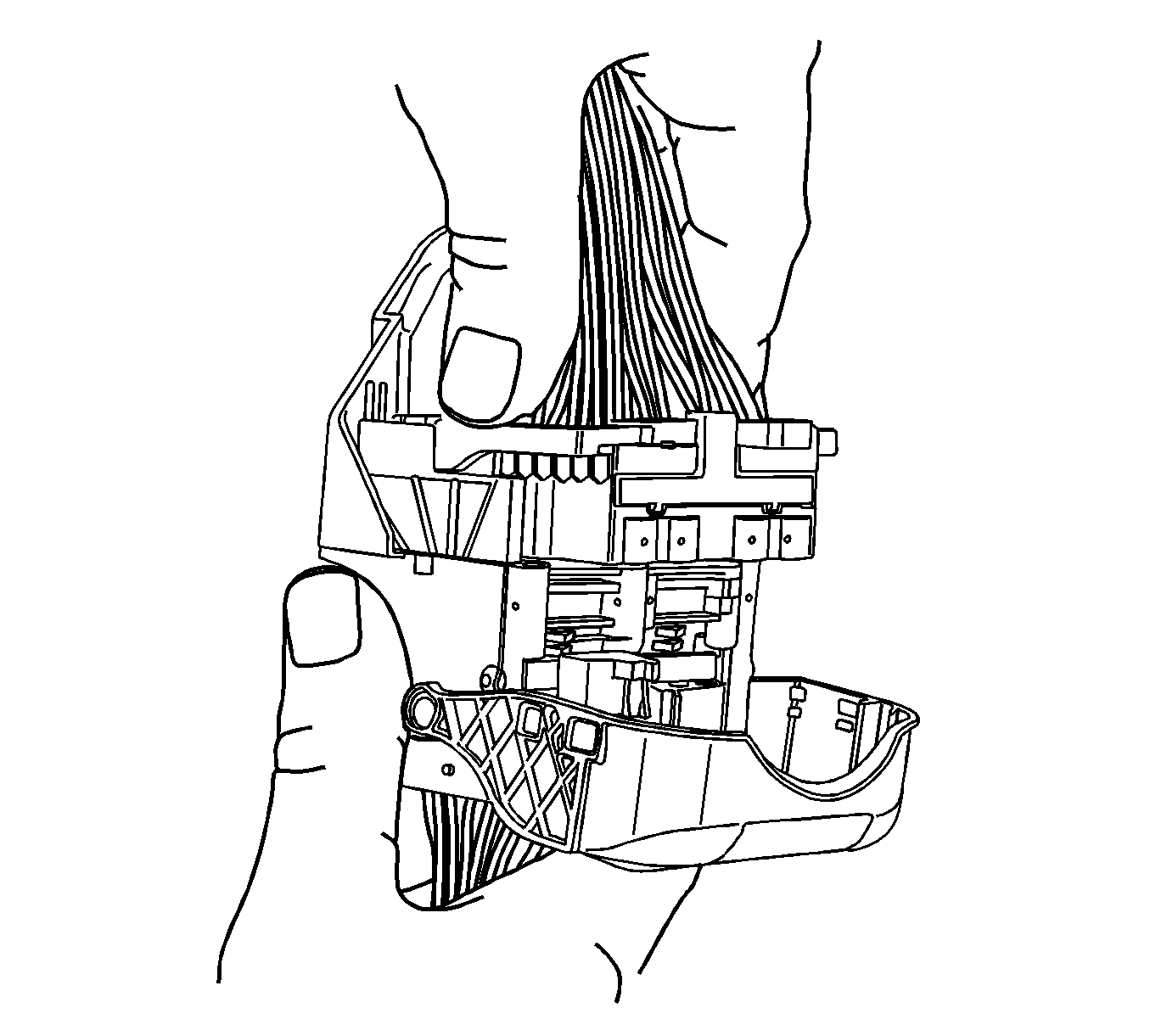
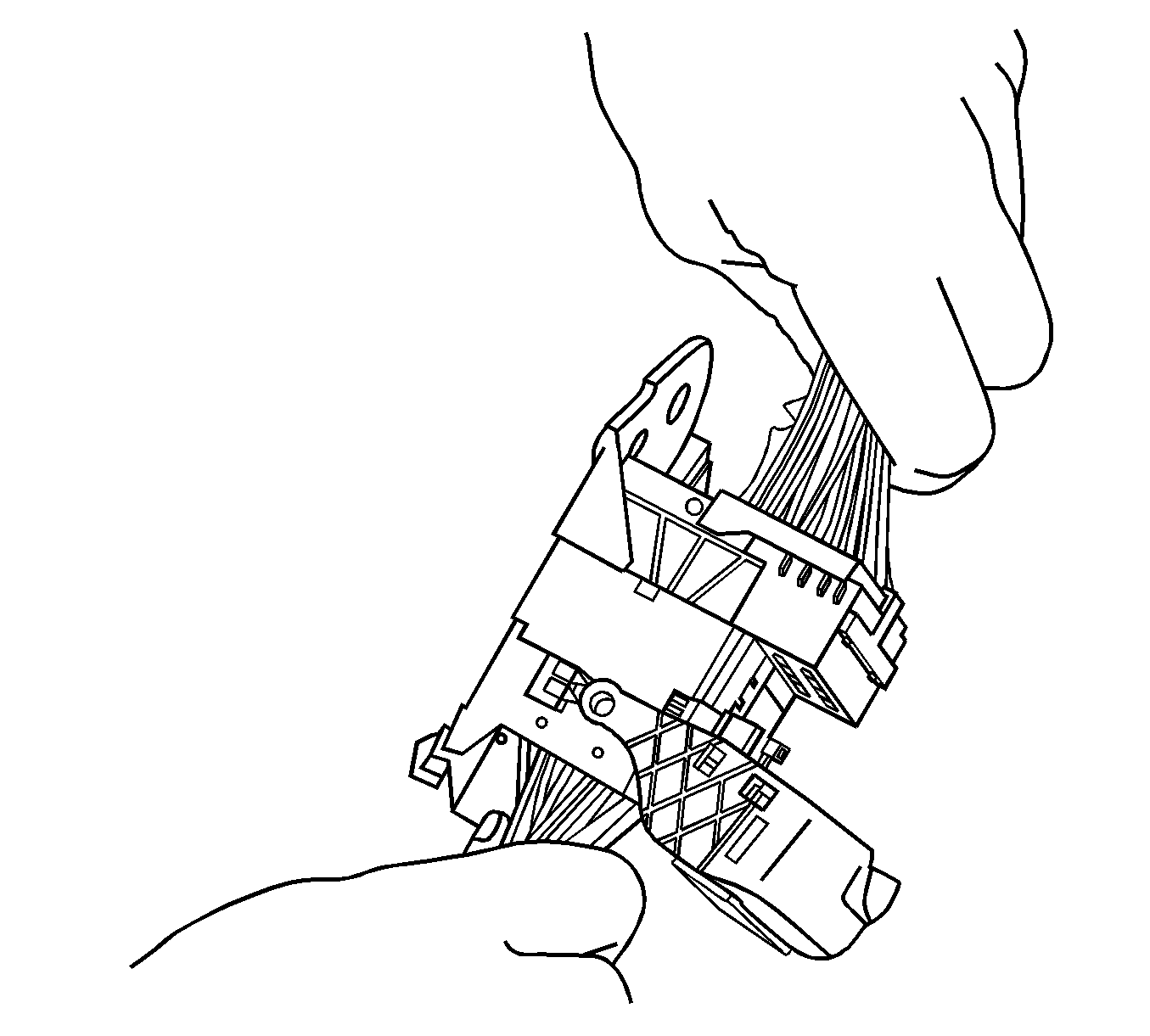
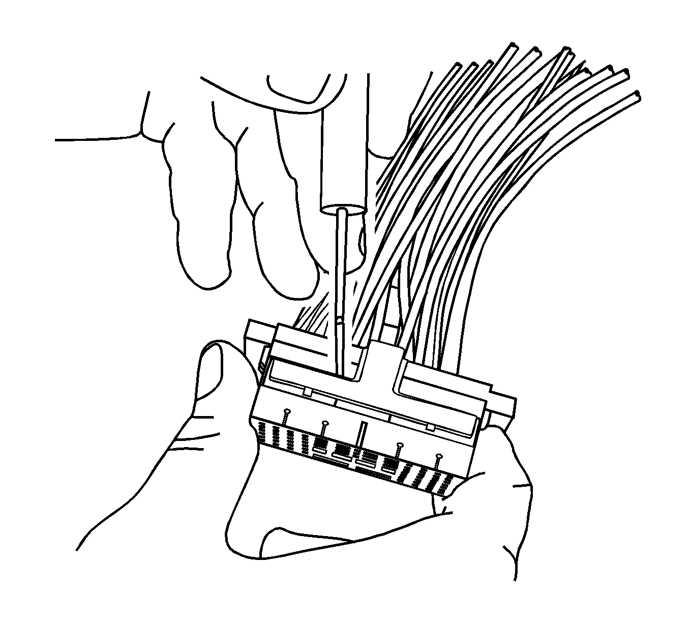
Note: During assembly the TPA will not fully seat if any terminal is not fully seated.
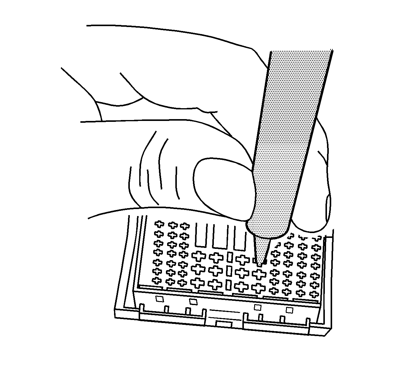
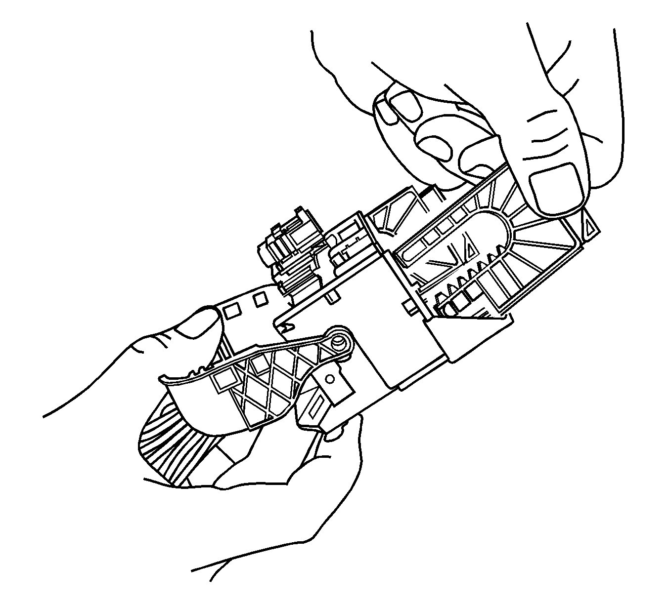
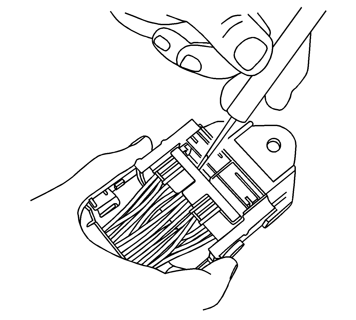
Note: During assembly the TPA will not fully seat if any terminal is not fully seated.
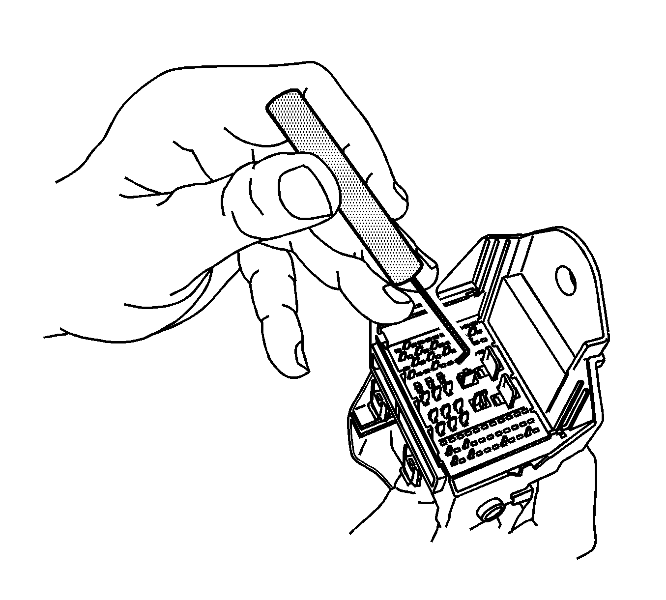
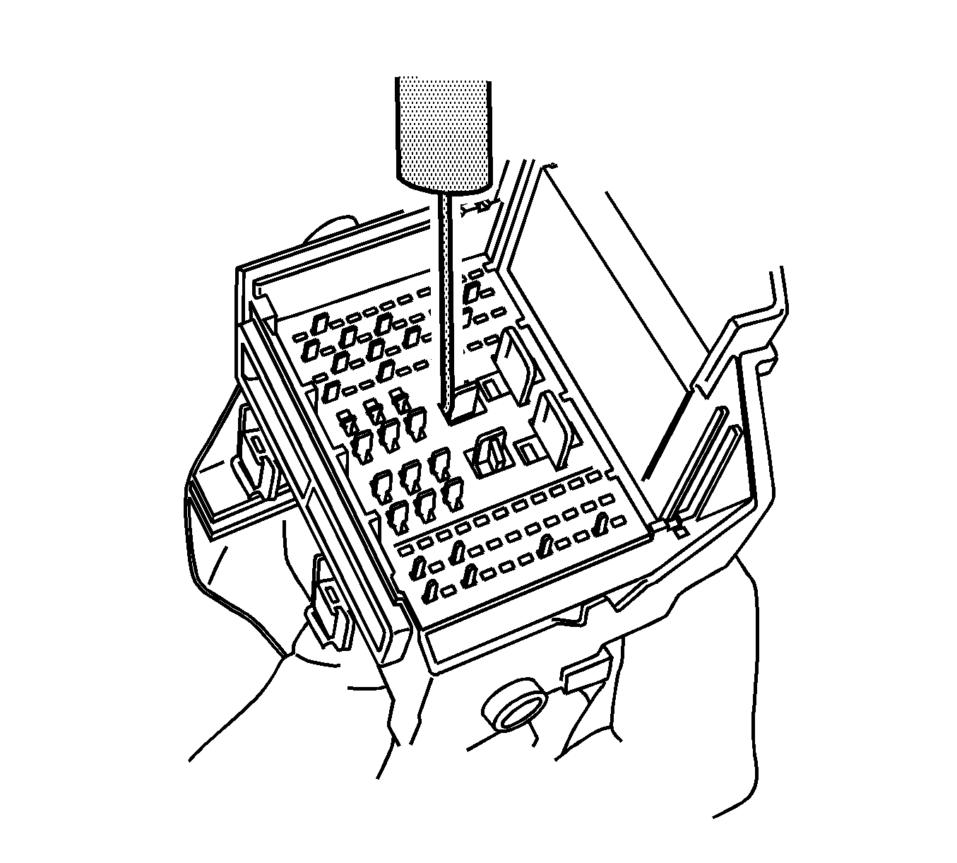



Terminal Repair Procedure
Use the appropriate terminal and crimper in the J-38125 in order to replace the terminal.
Tyco/AMP Connectors Seat
Special Tools
J-38125 Terminal Repair Kit
Removal Procedure
- Grasp the locking slide lever and pull outward from the end of the connector.
- As the slide lever is pulled out the mating connector is lifted from the seated position.
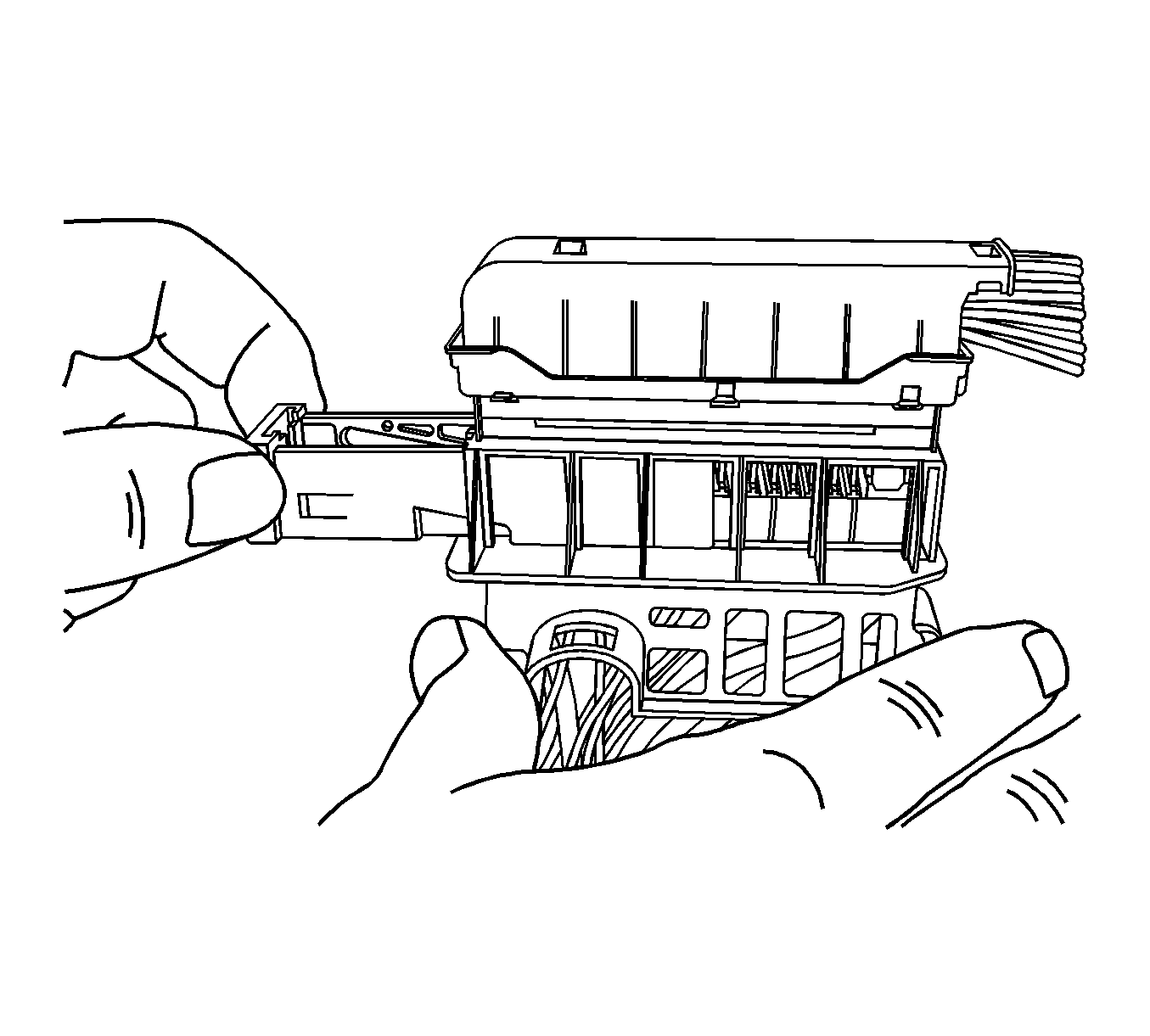
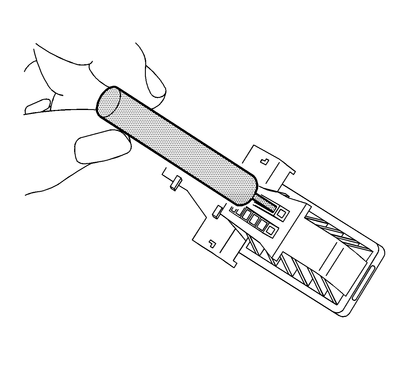
- Using terminal release tool J 38125-11A or equivalent, push the TPA tabs into the connector body.
- Pull the TPA from the connector body.
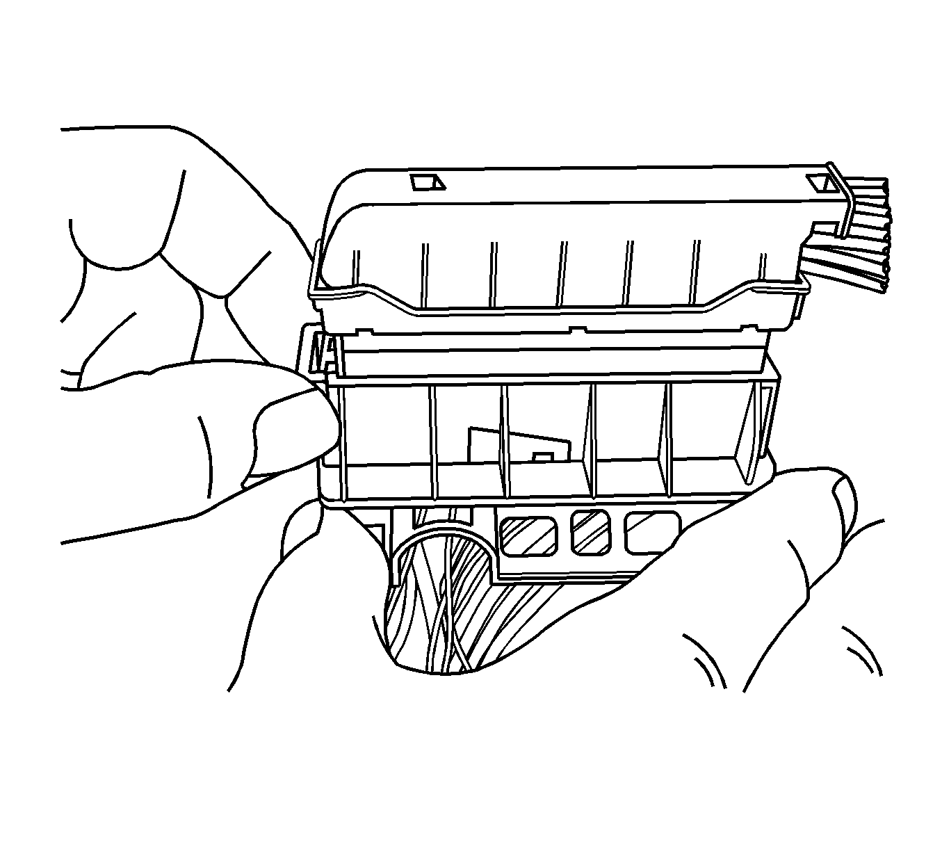
- Using terminal release tool J 38125-11A or equivalent, release the connector wire dress cover locking tab.
- With the lock tab released, lift the connector wire dress cover from the connector body.
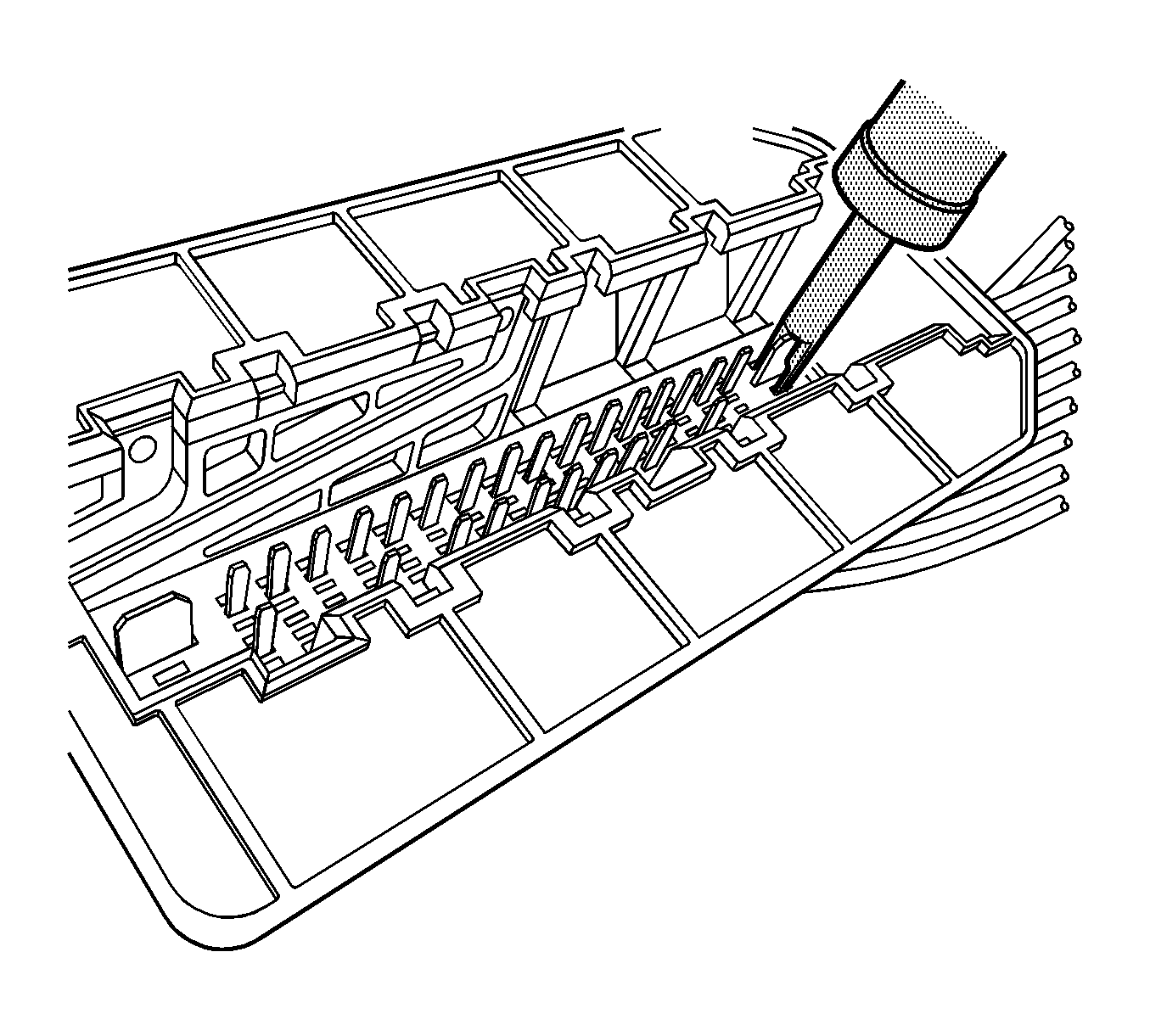
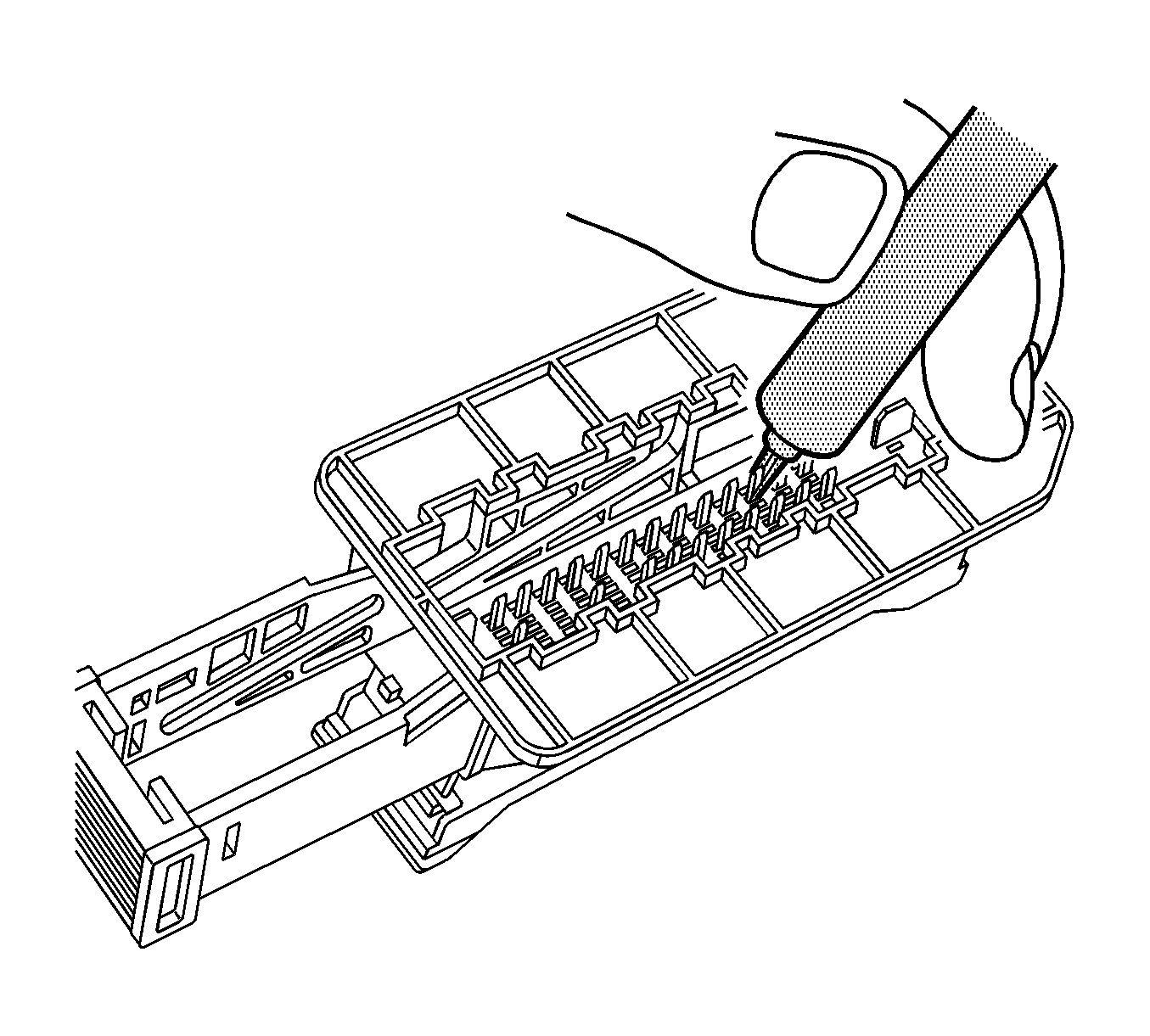
- Using terminal release tool J 38125-212, press the prongs into the holes each side of the terminal to be removed to release the lock tabs and pull the terminal out of the connector body.
- Using terminal release tool J 38125-560, press the prongs into the holes on each side of the terminal to be removed to release the lock tabs and pull the terminal out of the connector body.
- Using terminal release tool J 38125-556, press the prongs into the holes on each side of the terminal to be removed to release the lock tabs and pull the terminal out of the connector body.
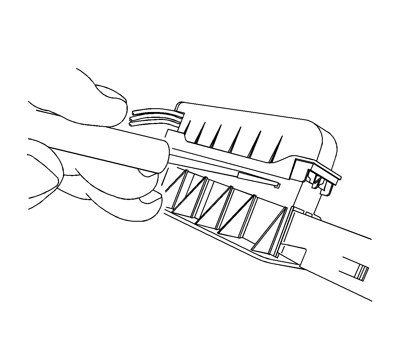
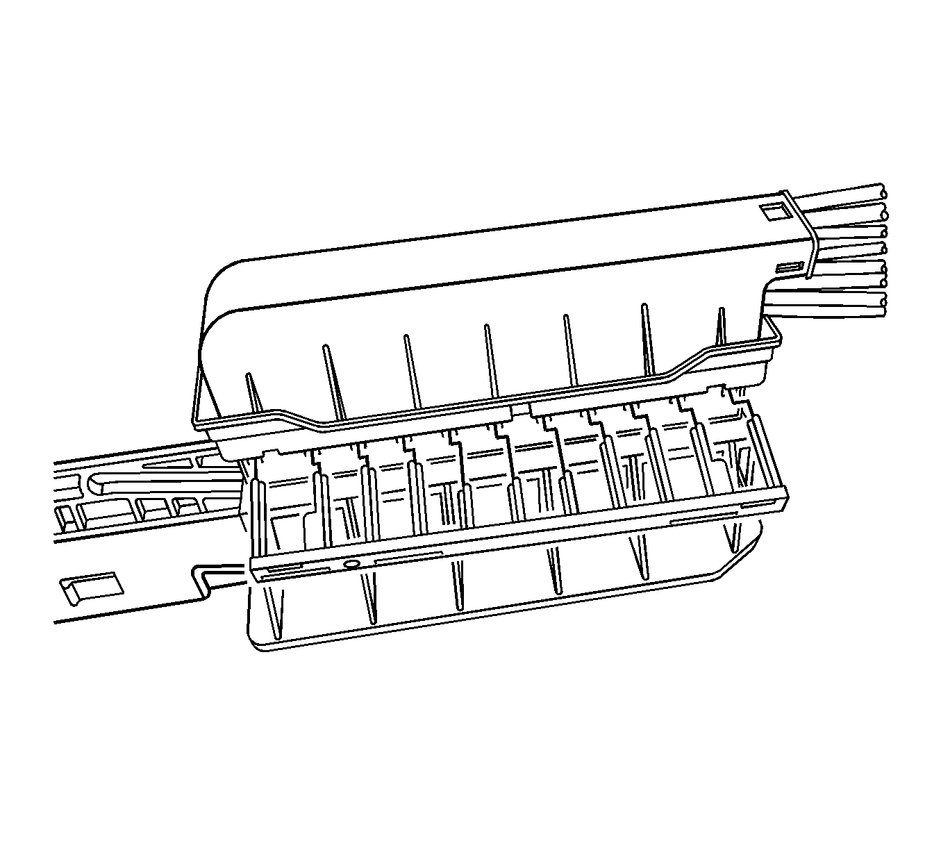
Note: TPA is keyed and can only be inserted in one direction.
Terminal Repair Procedure
Use the appropriate terminal and crimper in the J-38125 in order to replace the terminal.
Tyco/AMP Connectors SIR
Special Tools
J-38125 Terminal Repair Kit
Removal Procedure
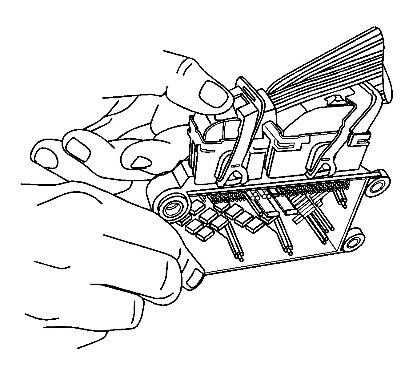
- Using your thumbs press down and slide the red CPA away from the connector lever.
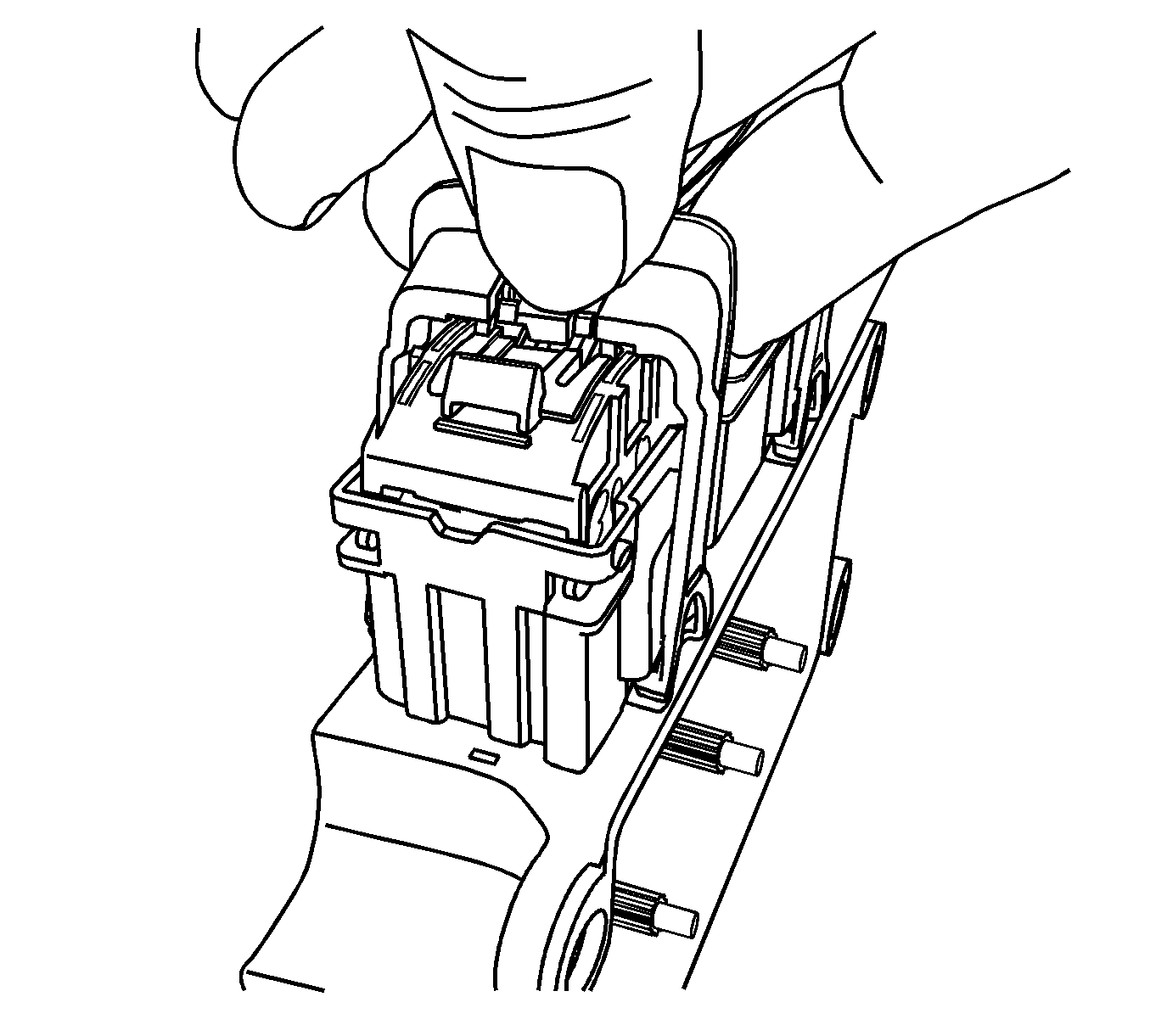
- Using your thumb press down on the locking tab and move the lever to the released position.
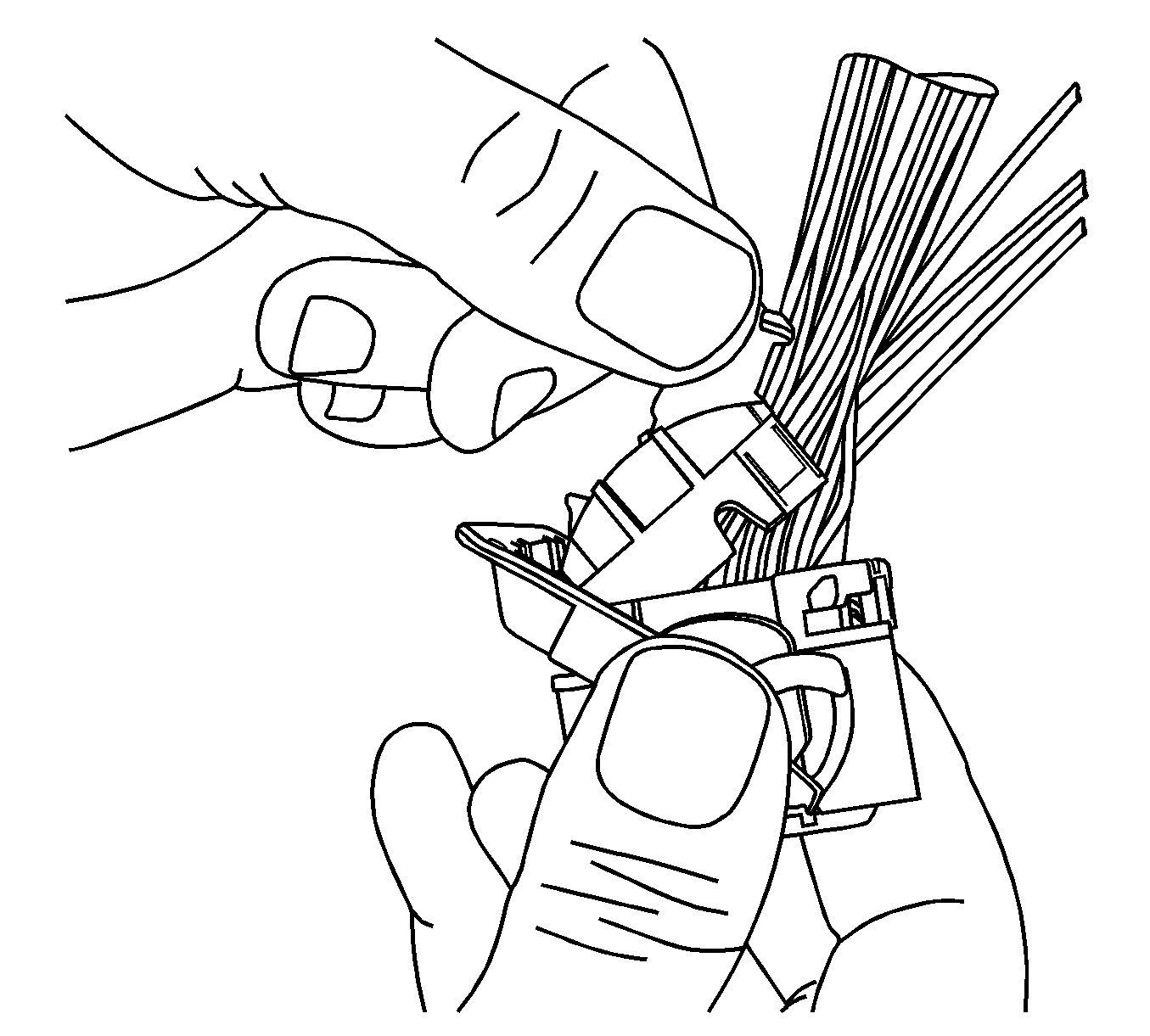
- Using terminal tool J-38125-11A or equivalent, release the wire dress cover locking tabs.
- Pivot connector wire dress cover while removing from the connector body.
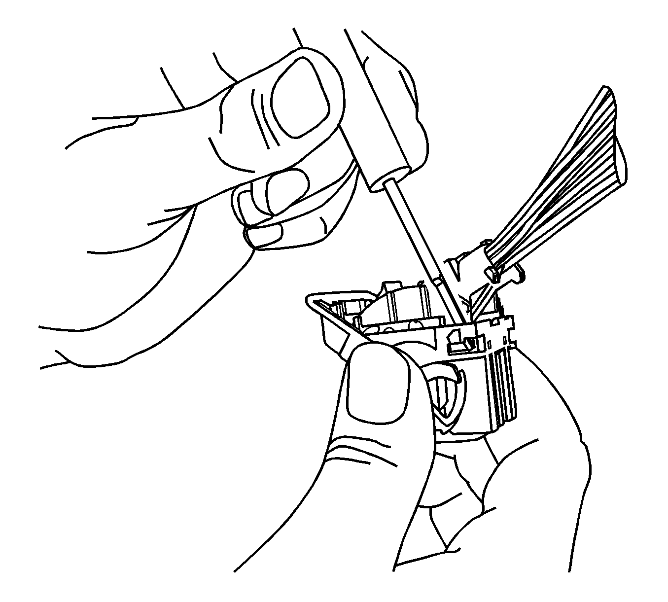
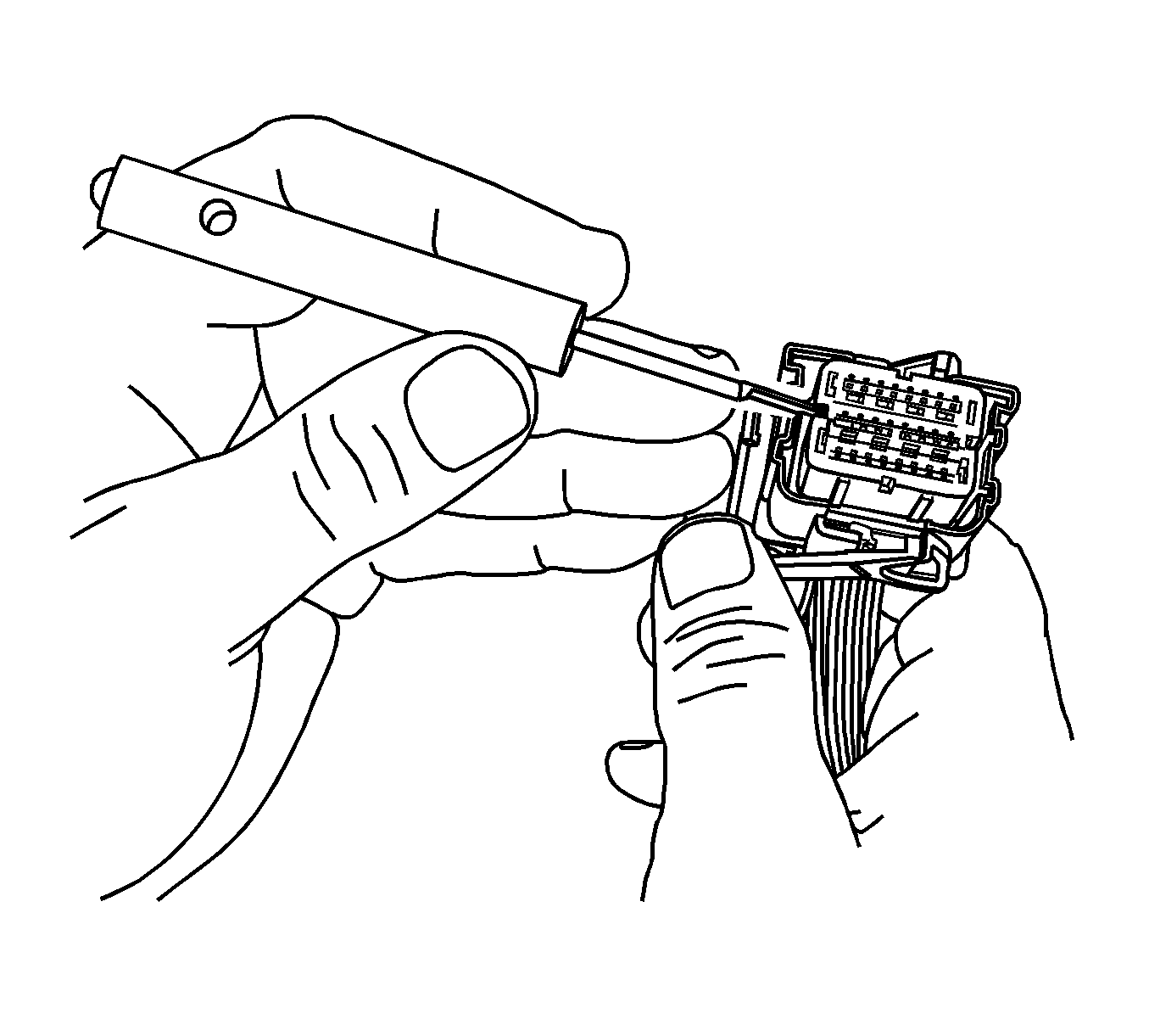
- Using terminal tool J-38125-11A or equivalent, remove the TPA by lifting straight off the connector body.
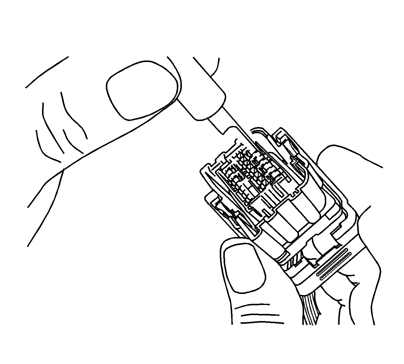
- Using terminal release tool J-38125-215A, place the tip of the tool on the outside edge next to the terminal and depress the lock tab and remove the rear of the connector body.
Terminal Repair Procedure
Use the appropriate terminal and crimper in the J-38125 in order to replace the terminal.
