For 1990-2009 cars only
Tools Required
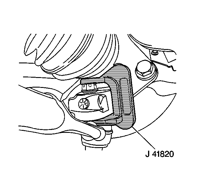
J 41820 Ball Joint Separator
Removal Procedure
- Install the engine support fixture. Refer to Engine Support Fixture .
- Remove the right front tire and wheel. Refer to Tire and Wheel Removal and Installation .
- Remove the right front splash shield. Refer to Engine Splash Shield Replacement .
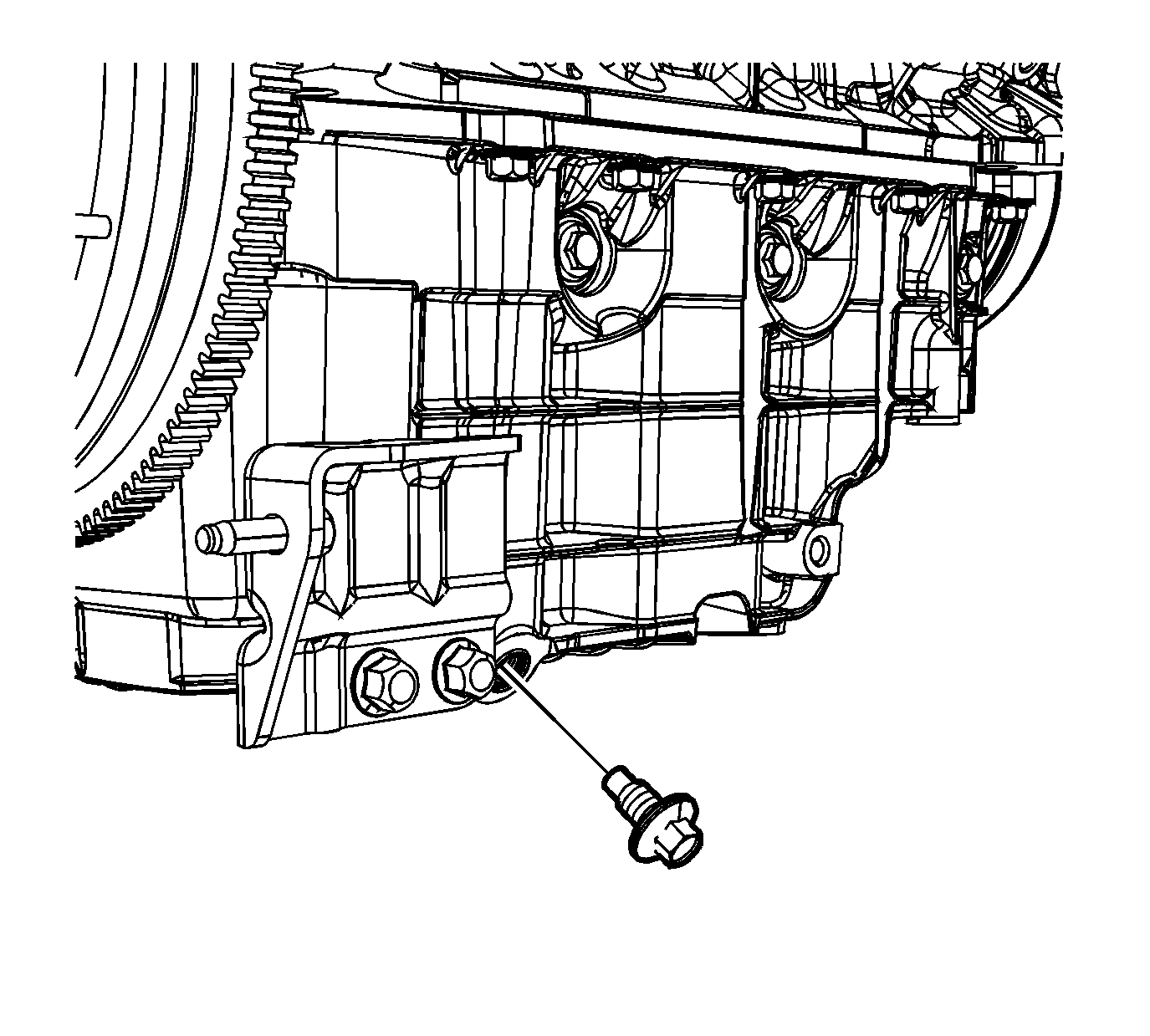
- Remove the oil pan drain plug.
- Drain the crankcase.
- Reinstall the oil pan drain plug until snug.
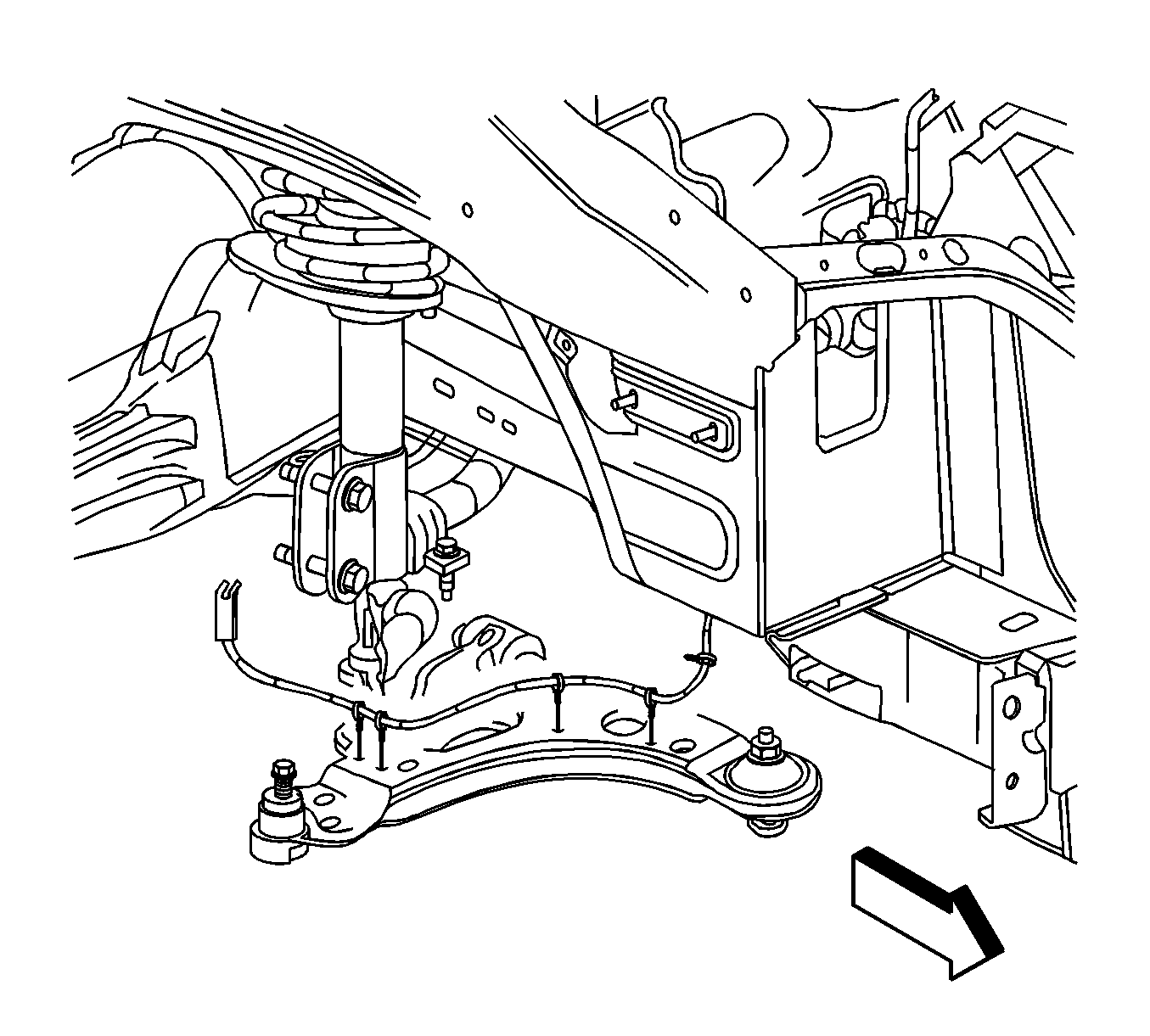
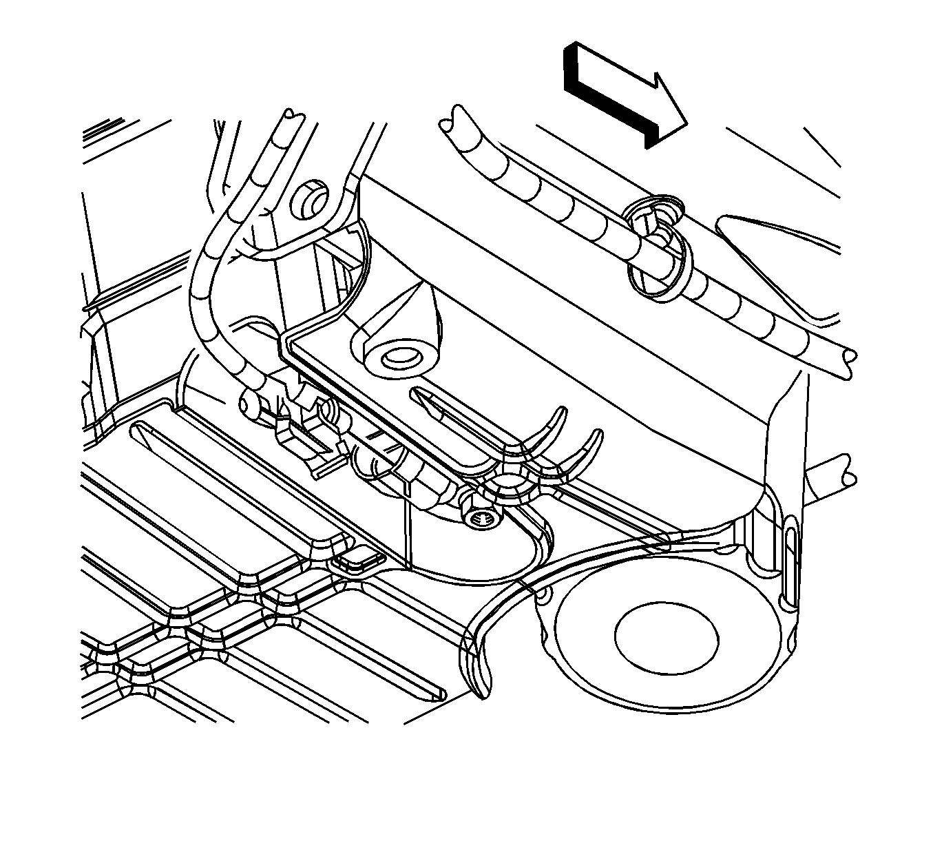
- Remove the engine harness clips from the right lower control arm.
- Remove and discard the lower ball joint castle nut cotter pin (1).
- Remove the lower ball joint castle nut (1).
- Install the over J 41820 the ball stud and lower control arm as shown.
- Rotate the ball stud nut counterclockwise in order to separate the ball stud from the steering knuckle
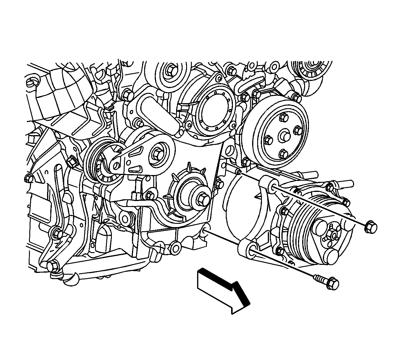
- Remove the air conditioning (A/C) compressor front bolt and nut.
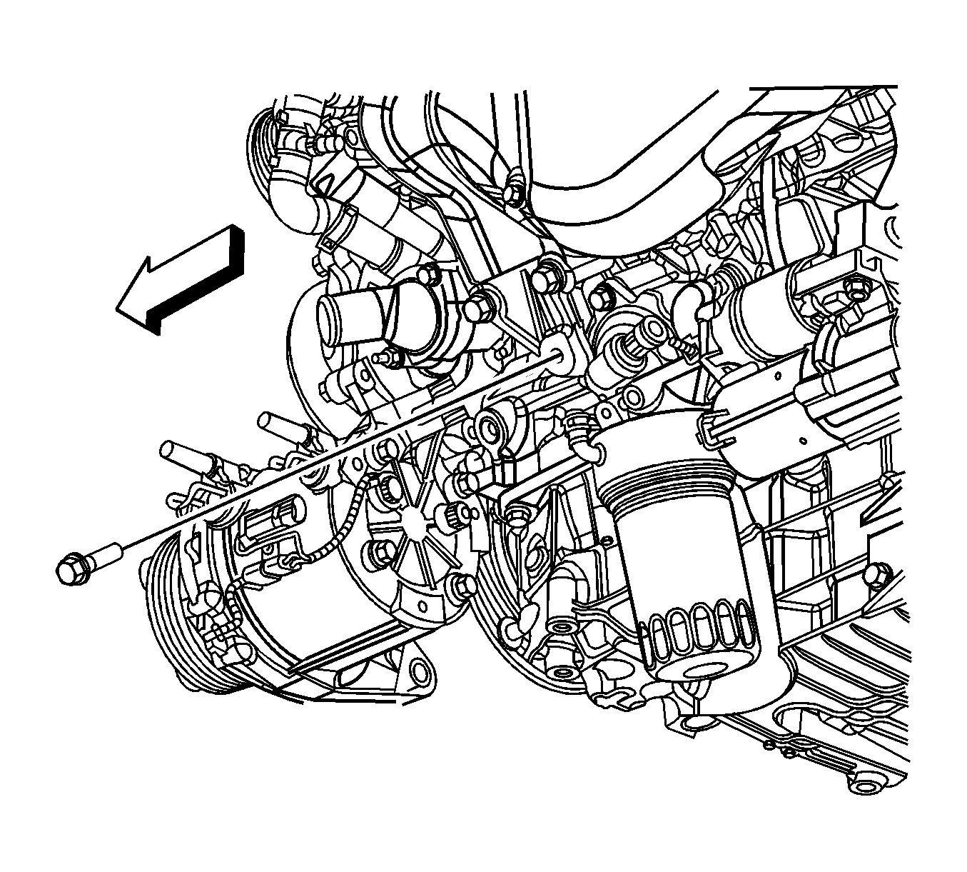
- Remove the A/C compressor rear bolt and position the compressor aside.
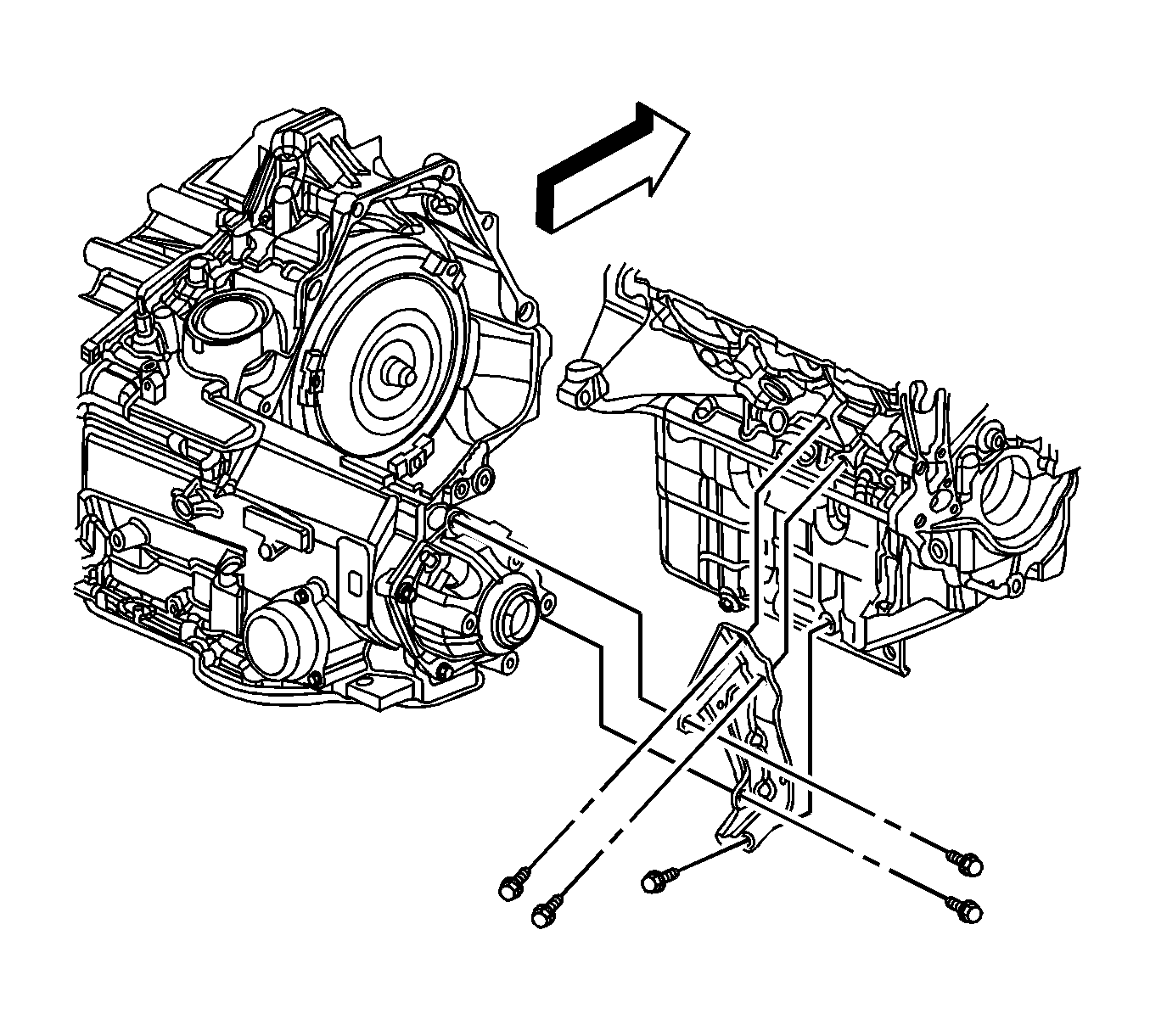
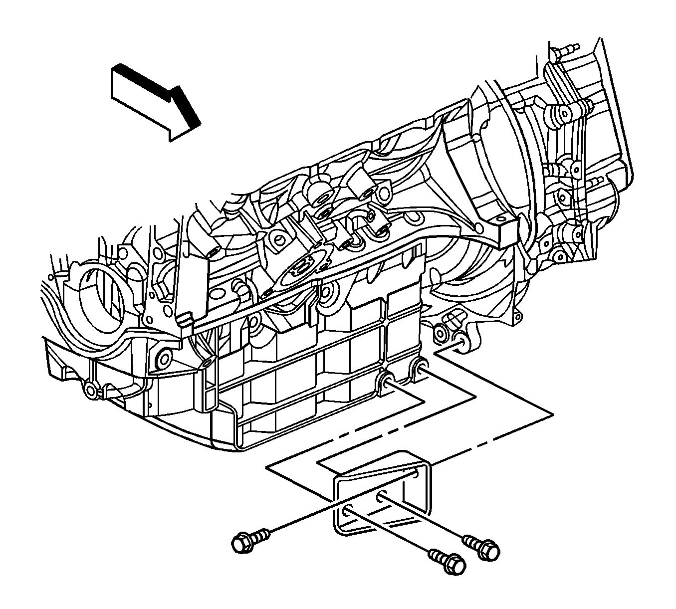
- Remove the transaxle brace to engine block/oil pan bolts.
- Remove the transaxle brace to transaxle bolts.
- Remove the transaxle brace.
- Remove the transaxle brace to oil pan bolts.
- Remove the transaxle brace to transaxle bolt.
- Remove the transaxle brace.
- Remove the starter. Refer to Starter Motor Replacement .
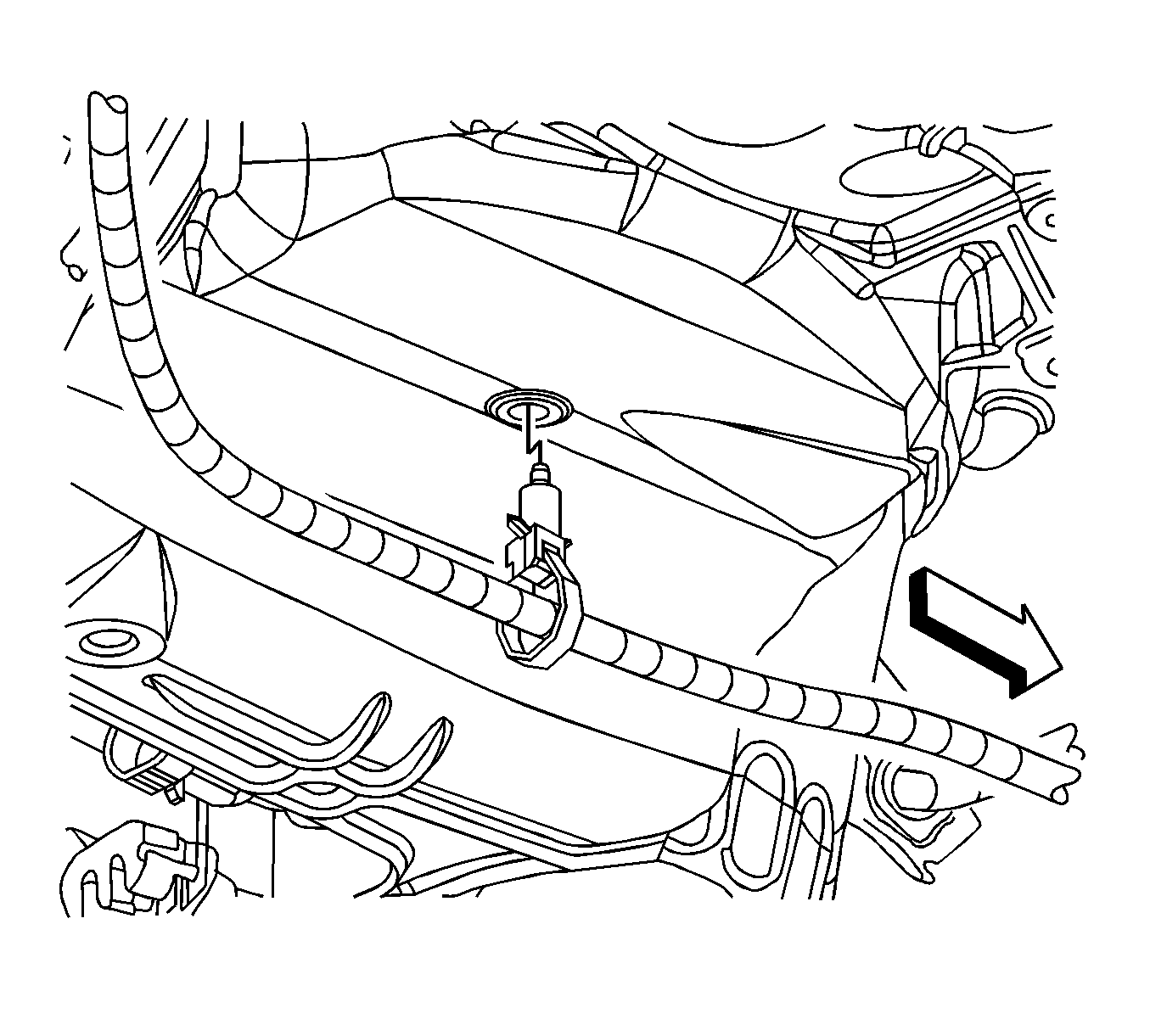
- Disconnect the engine harness electrical connector from the oil level sensor.
- Remove the engine harness clip from the oil pan.
- Remove the engine mount. Refer to Engine Mount Replacement .
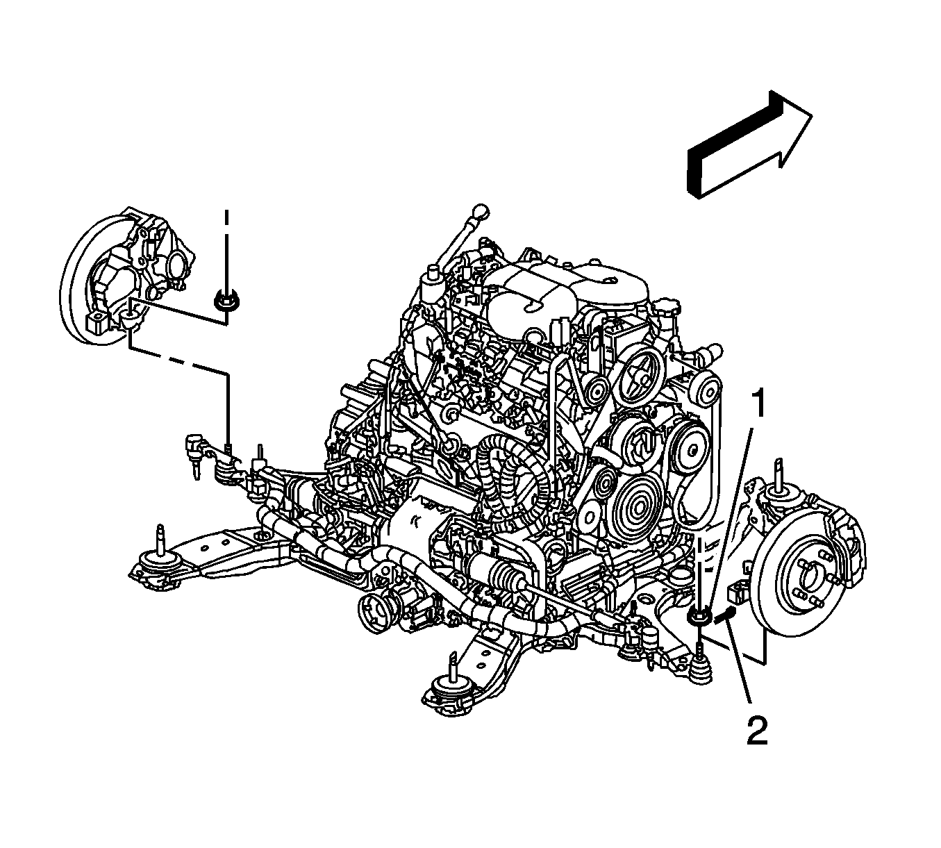
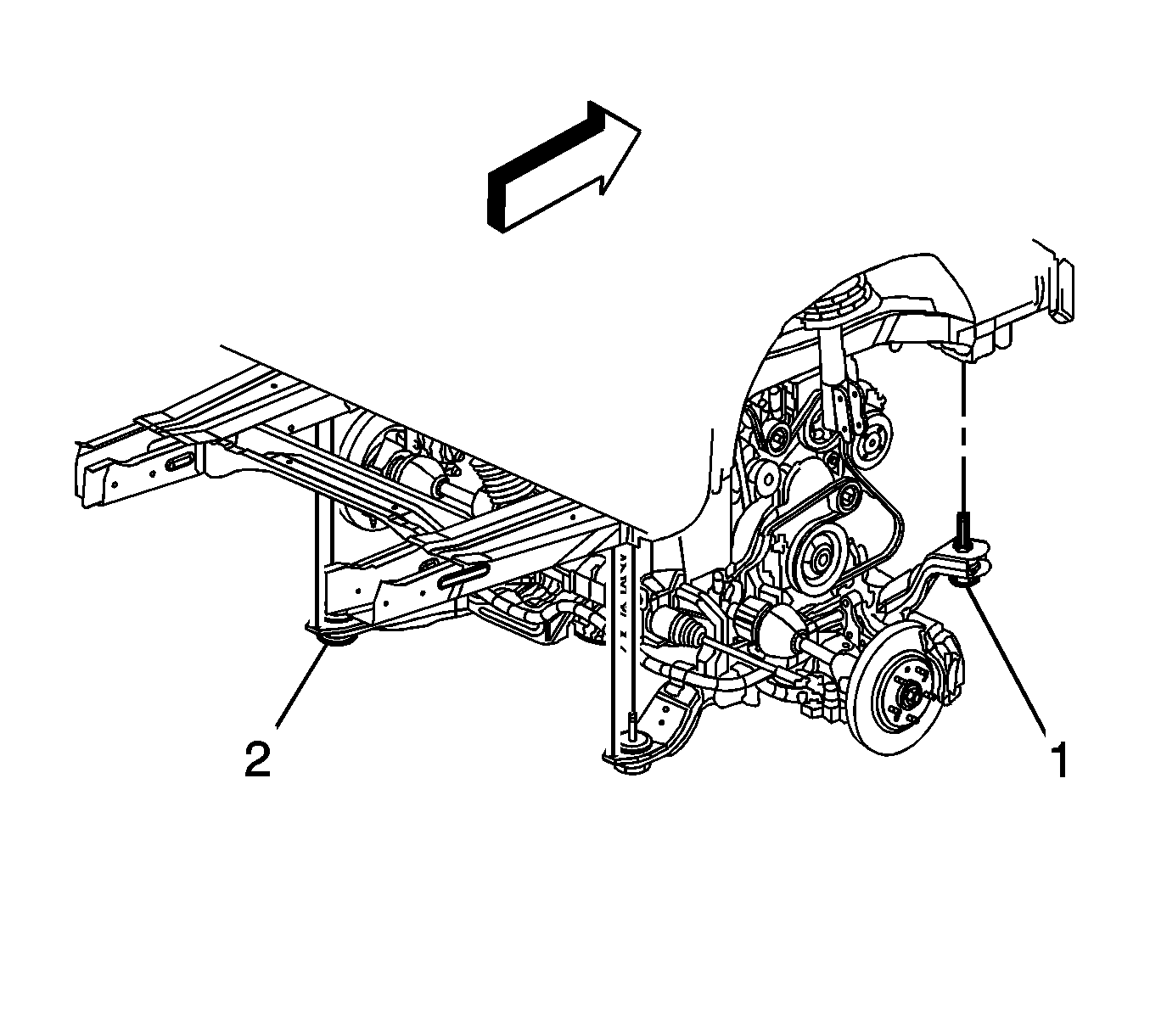
- Place adjustable jack stands under the frame.
- Loosen the left side frame bolts (2) and remove the right side frame bolts (1).
- Using the jack stands, lower the right side of the frame enough to remove the oil pan.
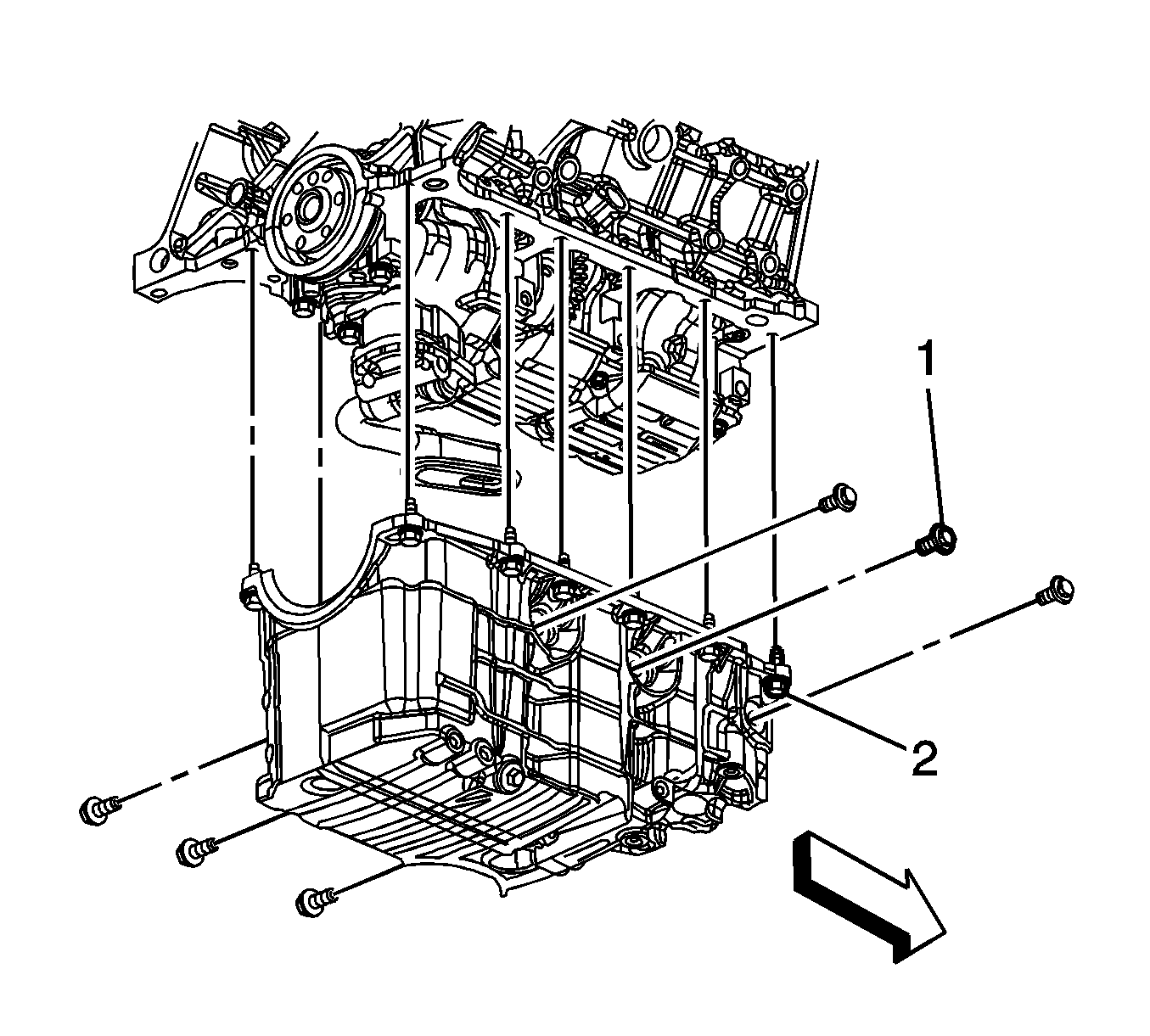
- Remove the oil pan side bolts (1).
- Remove the oil pan bolts (2).
- Remove the oil pan.
- Remove the oil pan gasket.
- Clean the following items:
| • | The oil pan flanges |
| • | The oil pan rail |
| • | The front cover |
| • | The rear main bearing cap |
| • | The threaded holes |
Installation Procedure
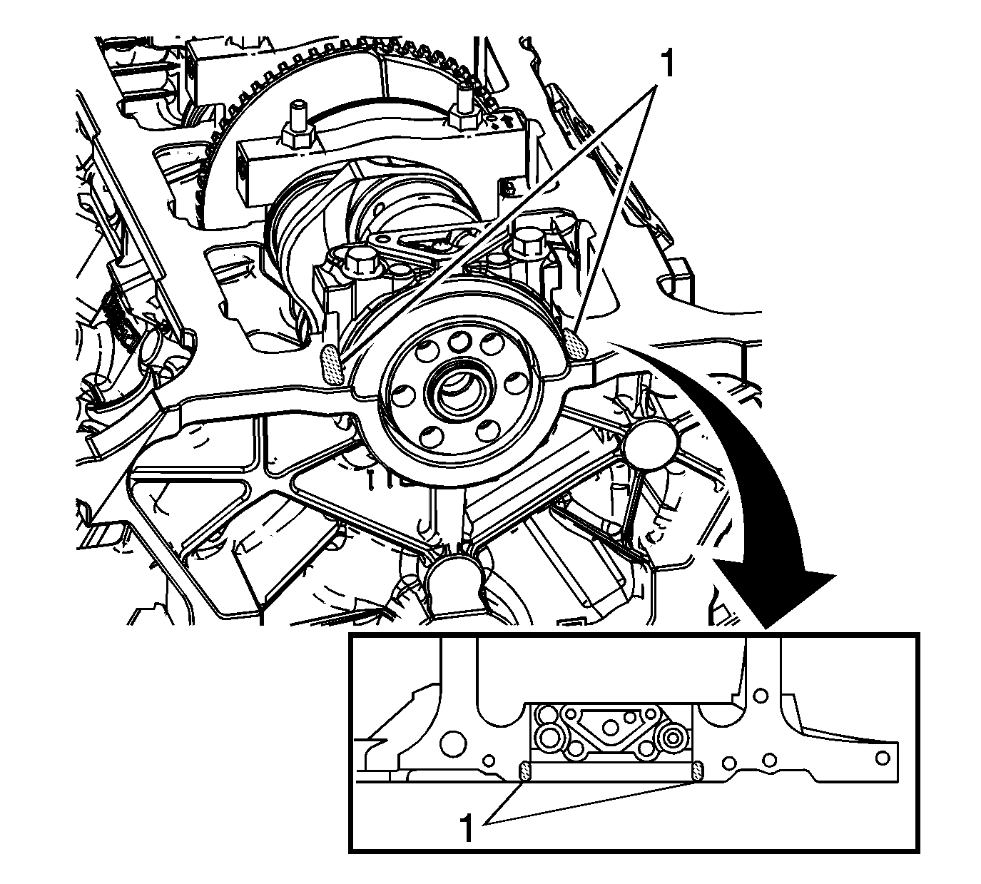
- Apply sealer to both sides of the crankshaft rear main bearing cap (1). Refer to Adhesives, Fluids, Lubricants, and Sealers . Press sealer into the gaps using a putty knife.
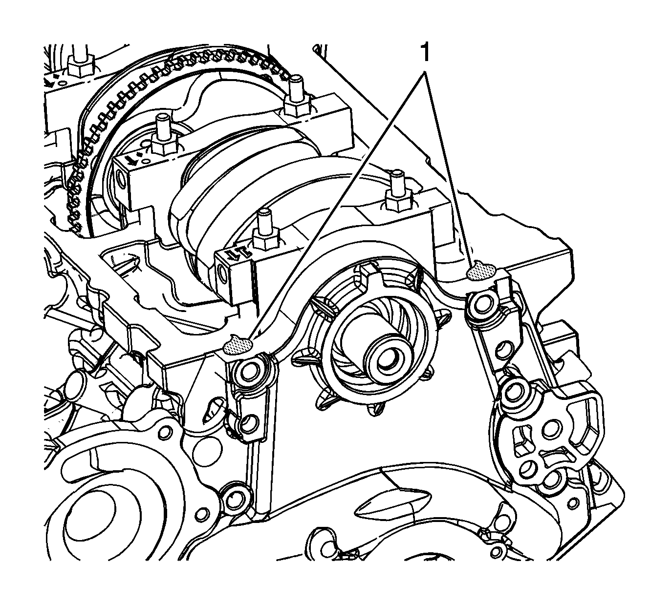
- Apply sealer to both sides of the front cover/block mating area (1). Refer to Adhesives, Fluids, Lubricants, and Sealers .
- Install the oil pan gasket.
- Install the oil pan.
- Install the oil pan bolts (2).
- Install the oil pan side bolts (1).
- Using the jack stands, raise the right side of the frame.
- Install and tighten the right side frame bolts (1) and tighten the left side frame bolts (2).
- Remove the adjustable jack stands from under the frame.
- Install the engine mount. Refer to Engine Mount Replacement .
- Install the engine harness clip to the oil pan.
- Connect the engine harness electrical connector to the oil level sensor.
- Install the starter. Refer to Starter Motor Replacement .
- Position the transaxle brace to the transaxle and oil pan.
- Install the transaxle brace to transaxle bolt.
- Install the transaxle brace to oil pan bolts.
- Position the transaxle brace to the transaxle and the engine block/oil pan.
- Install the transaxle brace to transaxle bolts.
- Install the transaxle brace to engine block/oil pan bolts.
- Position the A/C compressor over the front stud and install the A/C compressor front bolt and nut.
- Install the A/C compressor rear bolt.
- Install the lower ball joint to the steering knuckle.
- Install the lower ball joint castle nut (1).
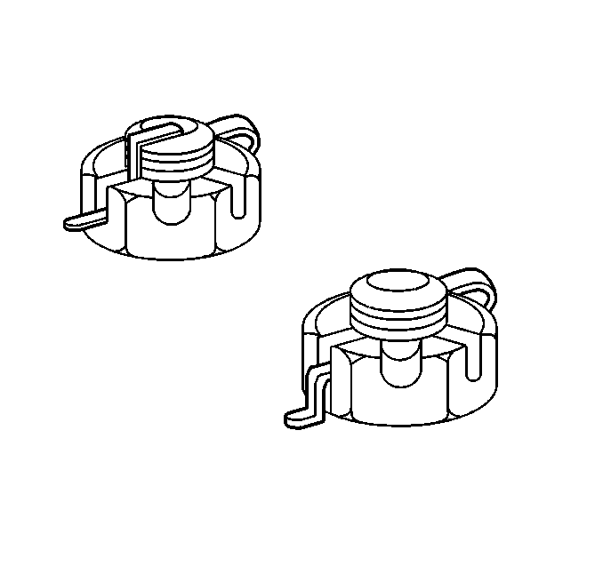
- If necessary, tighten the castle nut in order to align one of the slots (1) to the ball joint stud pin hole (2) as shown.
- Install a NEW cotter pin to the castle nut and ball joint stud.
- Bend the NEW cotter pin ends as shown in either example.
- Install the engine harness clips to the right lower control arm.
- Install the right front splash shield. Refer to Engine Splash Shield Replacement .
- Install the right front tire and wheel. Refer to Tire and Wheel Removal and Installation .
- Remove the engine support fixture. Refer to Engine Support Fixture .
- Fill the crankcase with NEW oil.

Notice: Refer to Fastener Notice in the Preface section.
Tighten
Tighten the bolts to 25 N·m (18 lb ft).
Tighten
Tighten the bolts to 50 N·m (37 lb ft).

Tighten
| • | Tighten the front frame bolts to 130N·m (96 lb ft). |
| • | Tighten the rear frame bolts to 240 N·m (177 lb ft). |


Tighten
Tighten the bolts to 43 N·m (32 lb ft).

Tighten
Tighten the bolts to 43 N·m (32 lb ft).

Tighten
Tighten the bolt/nut to 50 N·m (37 lb ft).

Tighten
Tighten the bolt to 50 N·m (37 lb ft).

Tighten
Tighten the nut to 55 N·m (40 lb ft).
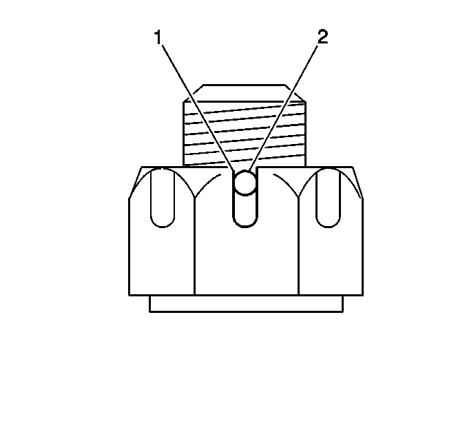
Important: Do not loosen the castle nut in order to align the slots to the ball joint stud pin hole.
