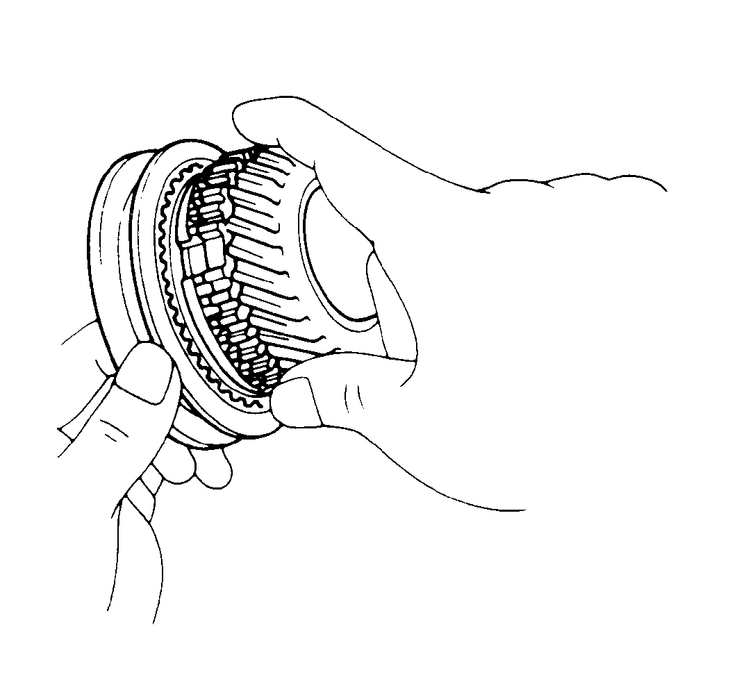
- Apply GM P/N 1052271 lightly as you assemble each part.
- Install the following parts onto the input shaft:
| • | The needle roller bearing |
| • | The number 2 hub sleeve assembly |
- Place the synchronizer ring on the gear. Align the clutch hub grooves with the projection on the synchronizer ring.
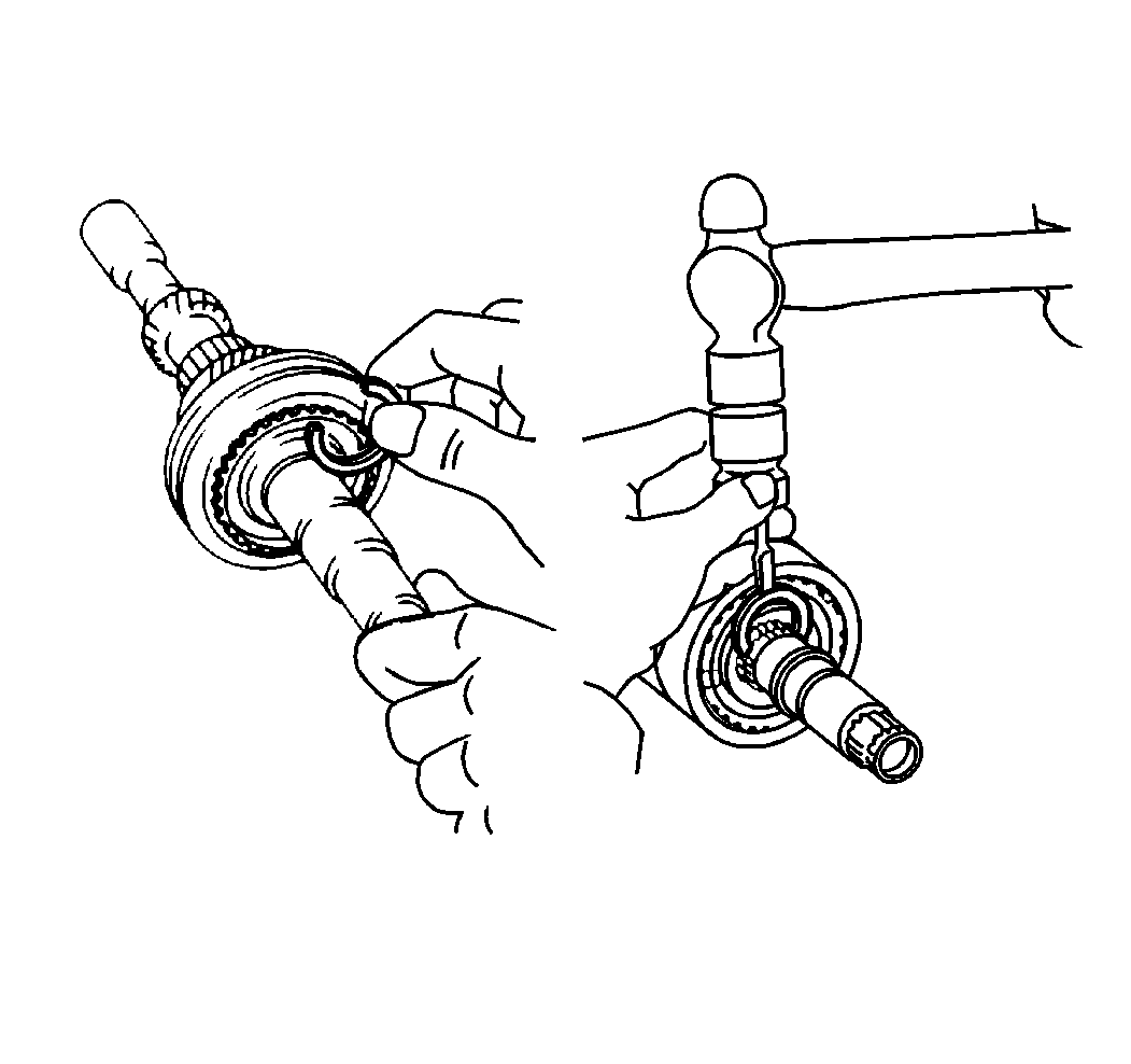
- Choose a selective snap ring that will allow minimum axial play. Refer to
Transmission Specifications
.
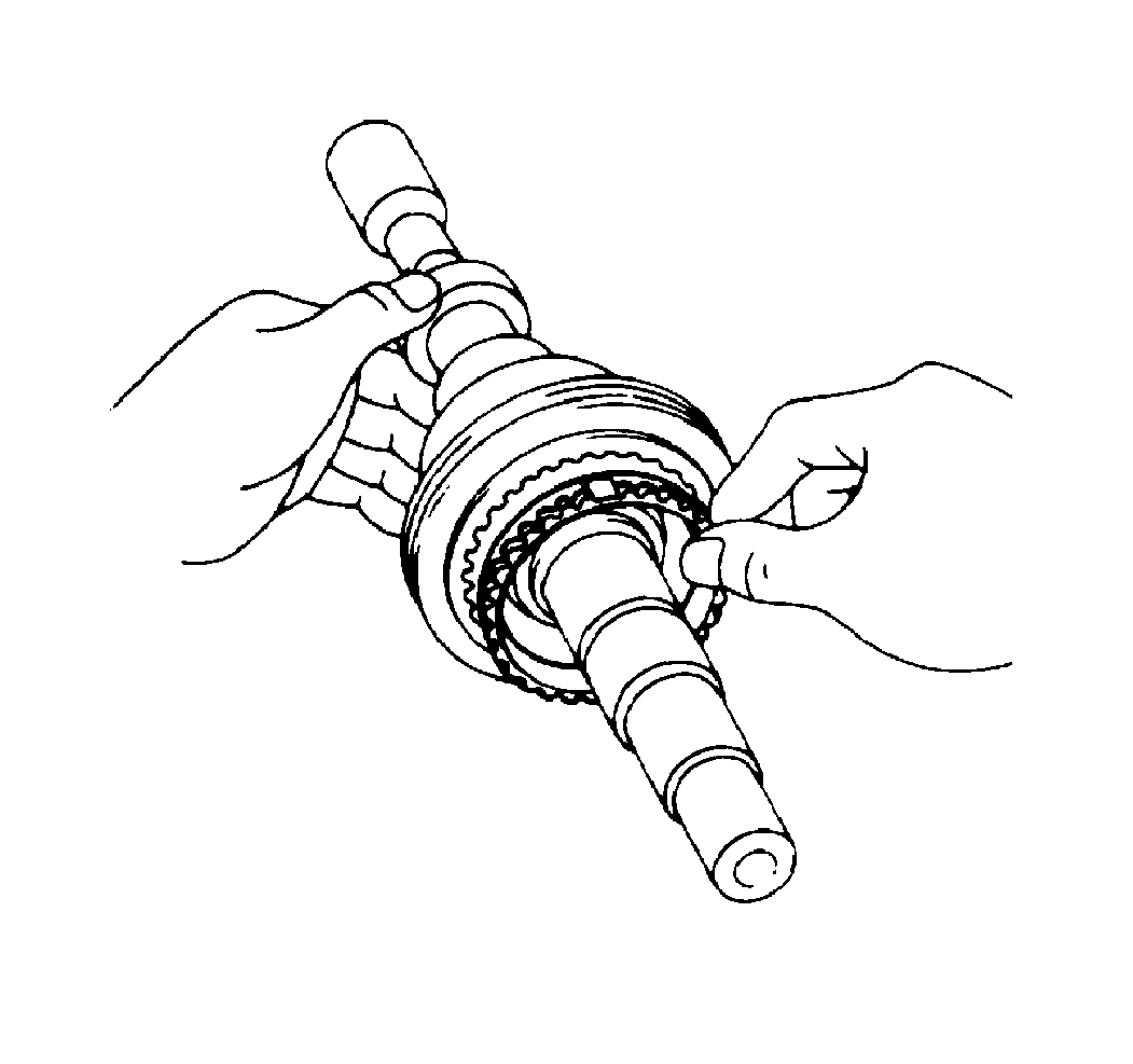
- Place the fourth gear synchronizer ring on the gear and align the clutch hub grooves with the projections
on the synchronizer ring.
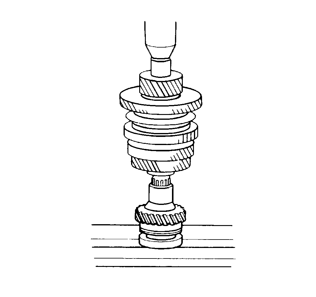
- Use a
J 22912-01
and a press to install the fourth gear and the radial ball bearing.
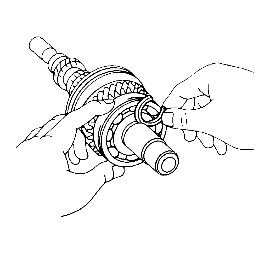
- Install the selective snap ring.
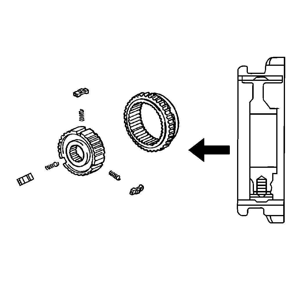
- If you are servicing any hub sleeve assembly, refer to the following procedure:
| 8.1. | Position the key springs so that the end gaps are not lined up. |
| 8.2. | Install the clutch hub and the shifting keys to the hub sleeve. |
| 8.3. | Install the shifting key springs under the shifting keys. |
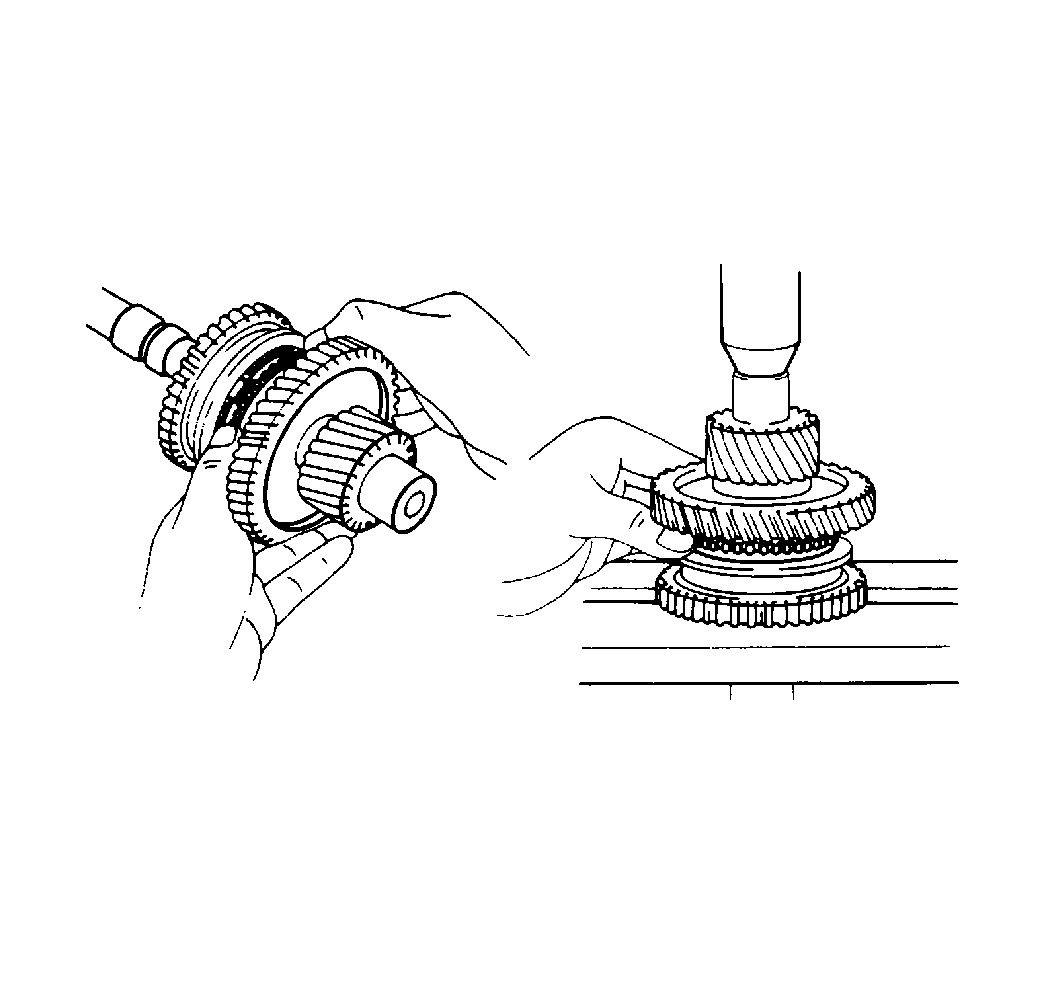
- Install the first gear locking ball in the shaft.
- Install the thrust washer securely over the locking ball.
- Install the synchronizer ring on the gear and align the clutch hub grooves with the projections on the synchronizer ring.
- Install the first gear and the number 1 hub sleeve.
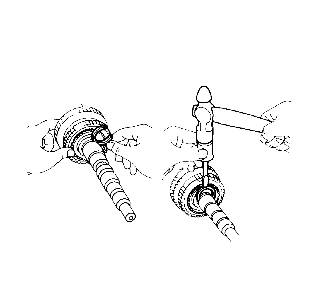
- Choose a selective snap ring that will allow the minimum axial play. Refer to
Transmission Specifications
.
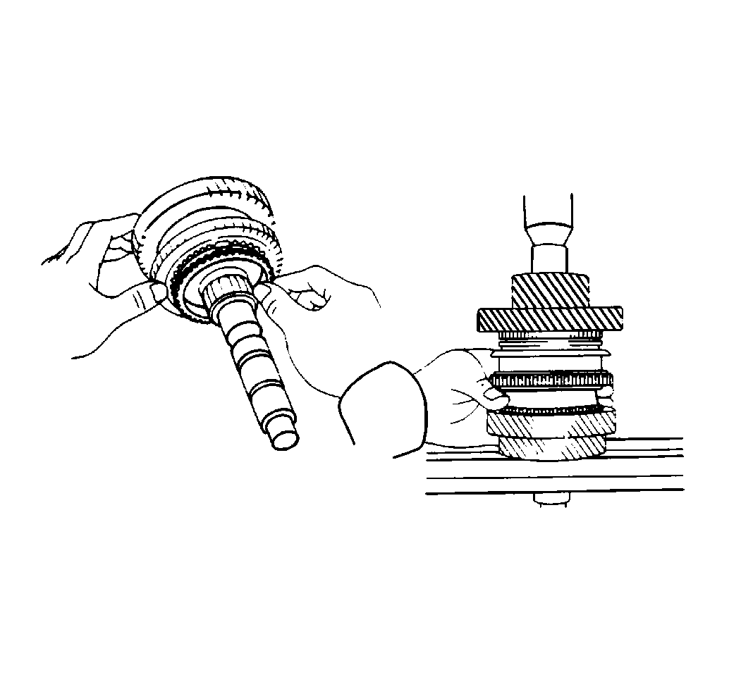
- Install the following parts:
- Install the third driven gear.
- Install the output gear spacer.
- Install the fourth driven gear and the bearing.
- Install the magnet.
- Install the oil receiver with two bolts. Finger tighten the bolts.
- Install the differential into the transaxle case.
- Inspect and adjust the side bearing preload. Refer to
Differential Replacement
.
Notice: Use the correct fastener in the correct location. Replacement fasteners
must be the correct part number for that application. Fasteners requiring
replacement or fasteners requiring the use of thread locking compound or sealant
are identified in the service procedure. Do not use paints, lubricants, or
corrosion inhibitors on fasteners or fastener joint surfaces unless specified.
These coatings affect fastener torque and joint clamping force and may damage
the fastener. Use the correct tightening sequence and specifications when
installing fasteners in order to avoid damage to parts and systems.
- Install the transaxle case.
Tighten
| • | Tighten the transaxle case bolts to 29 N·m (22 lb ft). |
| • | Tighten the oil receiver bolt to 11 N·m (97 lb in). |
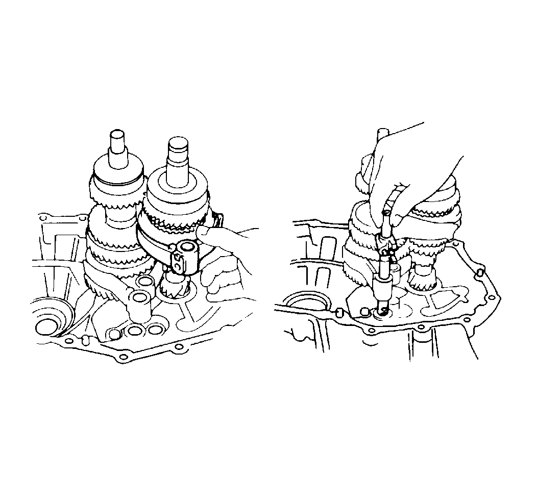
- Install the following components together:
- Install the following components:
- Place the number 1 shift forks into the groove of the number 1 hub sleeve.
- Place the number 2 shift forks into the groove of the number 2 hub sleeve.
- Insert the number 1 fork shaft into the number 1 shift fork hole.
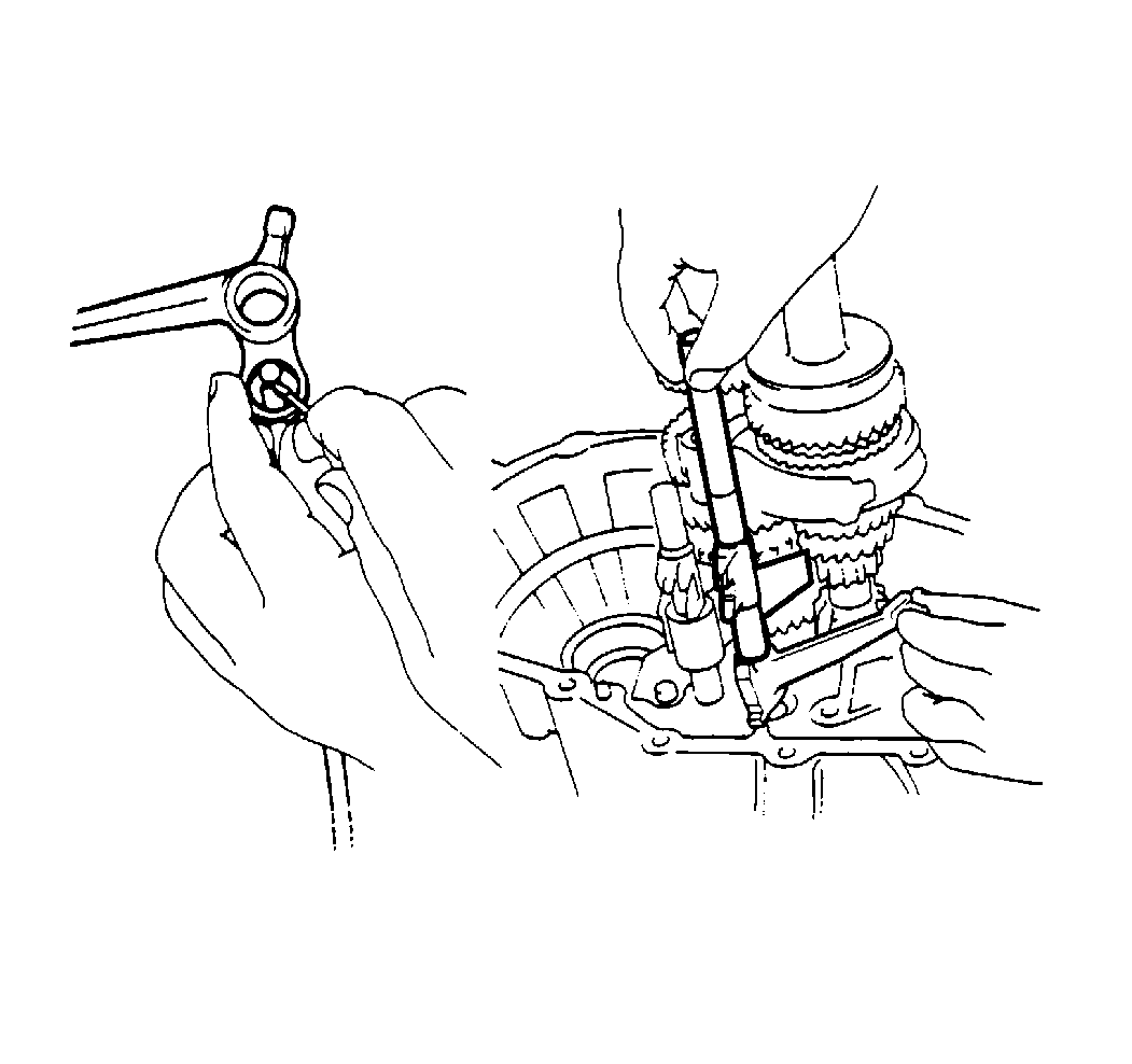
- Insert two interlock balls into the reverse shift fork.
- Install the following components:
| • | The number 3 shift fork shaft |
| • | The reverse shift fork. |
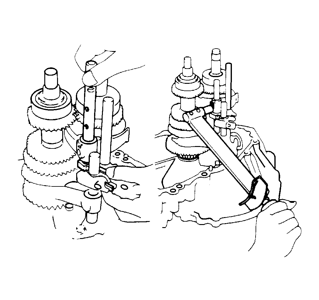
- Install the following components:
| • | The number 2 shift fork shaft |
- Insert the 3 lock bolts.
Tighten
Tighten the lock bolts to 16 N·m (12 lb ft).
- Install the three shift fork shaft snap rings.
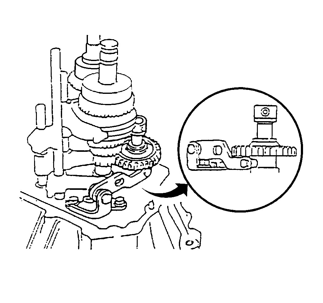
- Install the reverse shift arm.
Tighten
Tighten the reverse shift arm bolts to 17 N·m (13 lb ft).
- Install the reverse idle gear and shaft. Align the shaft to the idler gear mark.
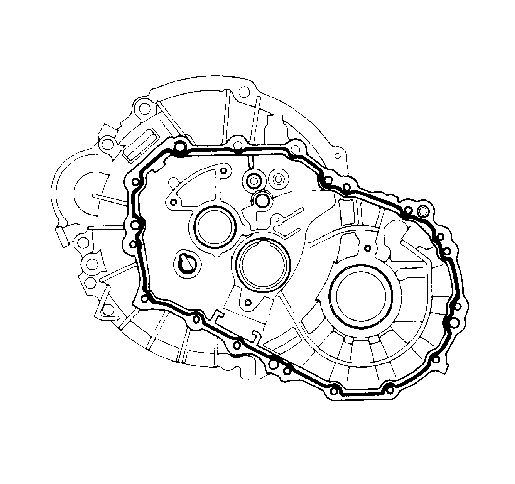
Important: Before you install the transaxle case, verify that no sealing material is on the case. Do not drop oil on the contacting surfaces.
- Apply GM P/N 1052756 Sealant.
- As soon as the sealant is applied, install the transaxle case.
- Insert 16 transaxle case bolts.
Tighten
Tighten the case bolts to 29 N·m (22 lb ft).
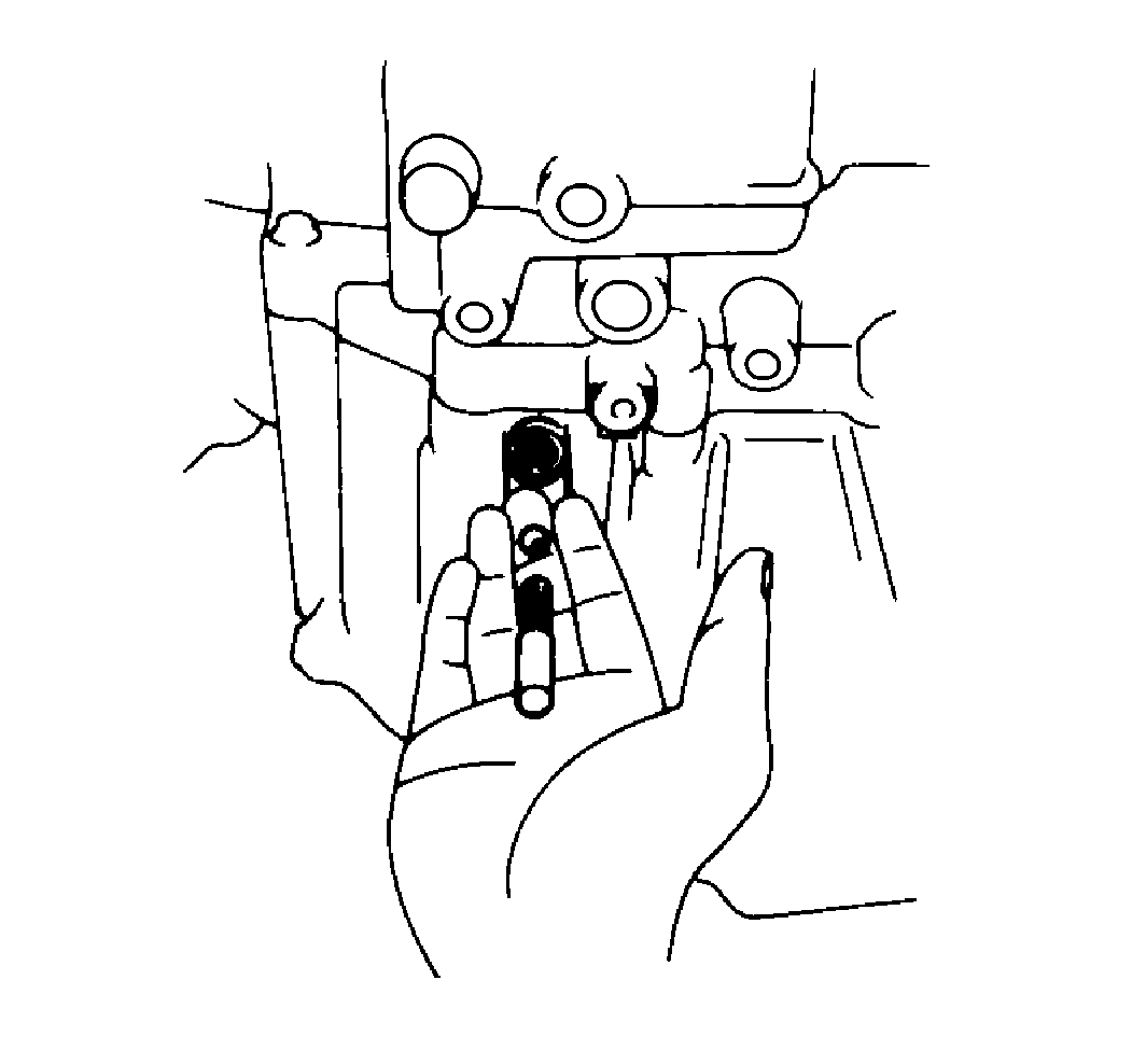
- Install the lock ball assemblies into the case.
- Apply GM P/N 1052624 sealant to the lock ball assembly plug threads.
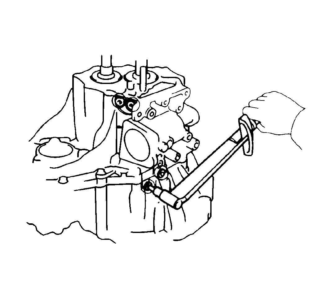
- Install the plugs.
Tighten
Tighten the plugs to 39 N·m (29 lb ft).
- Apply GM P/N 1052756 sealant to the reverse idler gear shaft lock bolt.
- Install the reverse idler gear shaft lock bolt.
Tighten
Tighten the bolt to 29 N·m (22 lb ft).
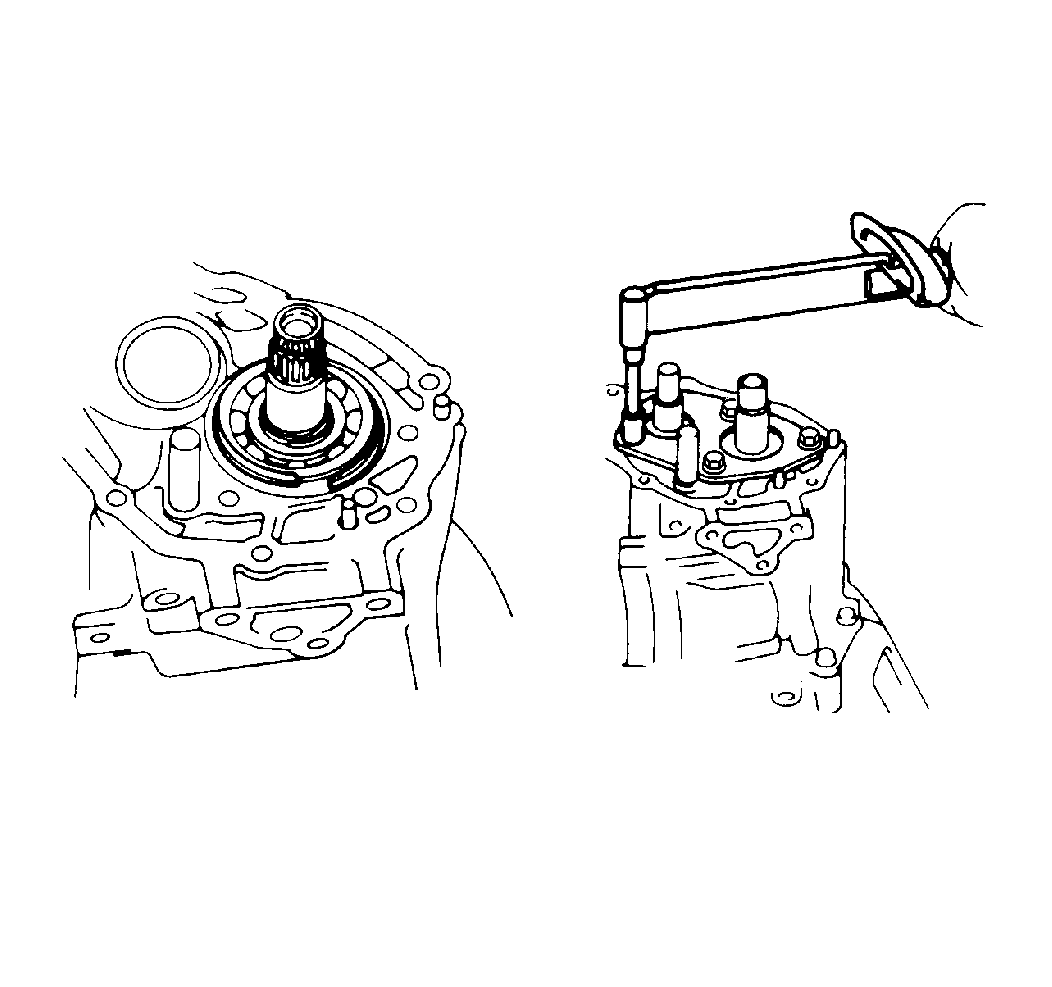
- Install the output shaft bearing snap rings.
- Install the snap ring number 2 fork shaft.
- Install the rear bearing retainer.
Tighten
Tighten the rear bearing retainer bolts to 27 N·m (20 lb ft).
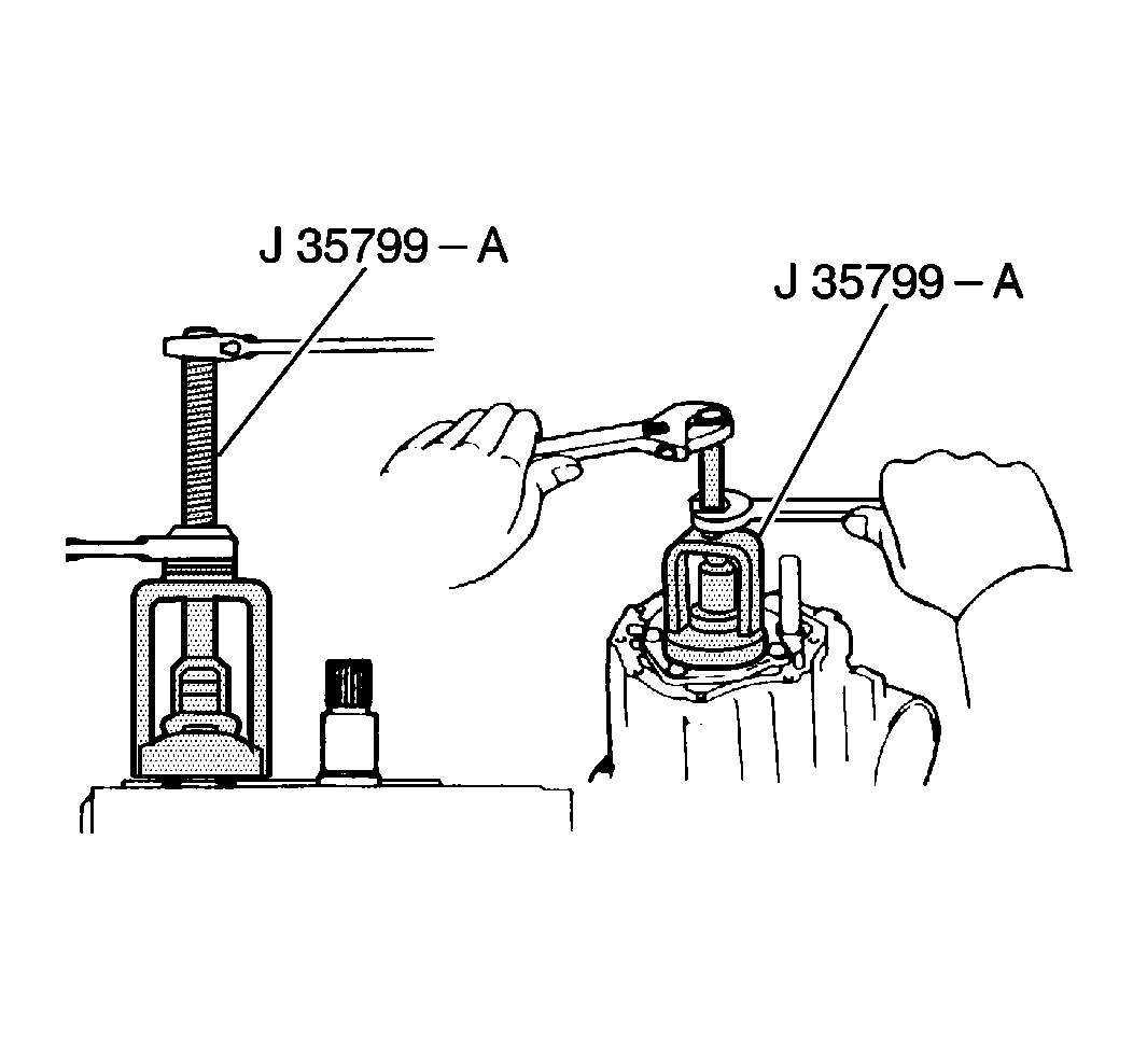
- Use a
J 35799-A
to install the fifth gear.
- Install the following components:
| • | The needle roller bearing |
| • | The fifth gear and synchronizer ring |
- Support the tip of the input shaft with a spacer in order to raise the transaxle assembly.
- Install the following components:
| • | The number 3 hub sleeve assembly |
- Align the synchronizer ring slots with the shifting keys.
- Install the hub sleeve assembly.
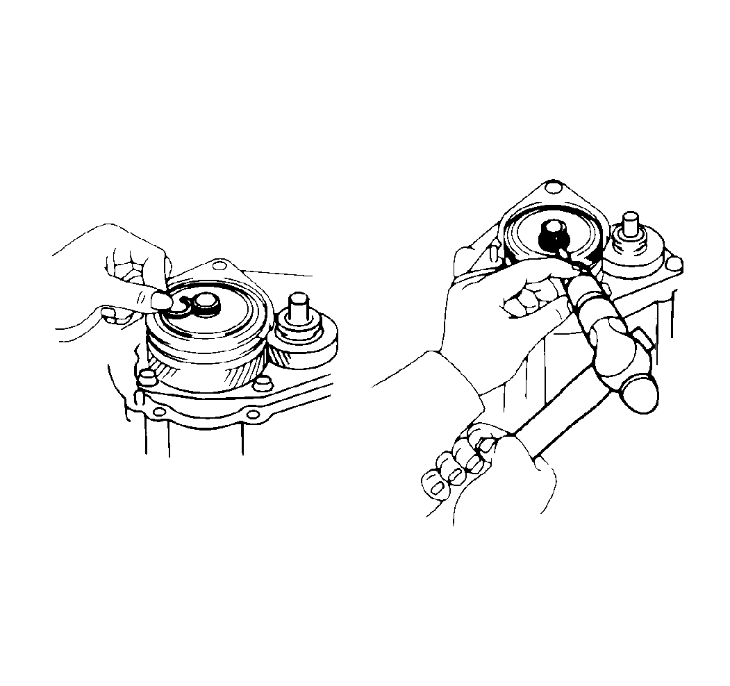
- Choose a selective snap ring that allows the minimum axial play. Refer to
Transmission Specifications
.
- Engage the gears.
- Install the locknut.
Tighten
Tighten the locknut to 118 N·m (87 lb ft).
- Disengage the gears.
- Stake the locknut.
- Install the number 3 fork shaft lock bolt.
Tighten
Tighten the number 3 fork shaft lock bolt to 16 N·m (12 lb ft).
- Install the shift and select lever assembly.
- Apply GM P/N 1052624 to the bolts. Insert the bolts into the shift and select lever assembly.
Tighten
Tighten the shift and select lever assembly bolts to 20 N·m (14 lb ft).
- Install the lock bolt.
Tighten
Tighten the lock bolt to 29 N·m (22 lb ft).
- Apply GM P/N 1052756 in an even 1 mm (0.04 in) bead on the case cover.
- Install the transaxle case cover.
Tighten
Tighten the case cover bolts to 18 N·m (13 lb ft).
- Install the front bearing retainer.
Tighten
Tighten the front bearing retainer bolts to 11 N·m (97 lb in).
- Install the backup switch using a
J 35451
.
Tighten
Tighten the backup switch to 40 N·m (30 lb ft).
- Install the VSS into the transaxle case. Secure the VSS with one retaining bolt.
Tighten
Tighten the VSS retaining bolt to 11 N·m (97 lb in).
- Release the fork and bearing.


