V5 AIR CONDITIONING AND REFRIGERANT SYSTEM DIAGNOSTICS

VEHICLES AFFECTED: 1984-89 MODELS EQUIPPED WITH V5 COMPRESSORS
The V5 is a variable displacement compressor that meets air conditioning demand by changing its stroke instead of cycling a clutch. A control valve located in the rear head of the compressor senses compressor suction pressure and causes the compressor to change stroke. Because the V5 Compressor runs constantly and does not cycle, the diagnostic procedure is different from that used for fixed displacement systems. By using this procedure, needless replacement of AC components may be avoided.
This quick check procedure was developed to help you diagnose V5 Compressor and refrigerant system conditions involving reduced cooling. It must be used in conjunction with the proper service manuals and performed in the sequence given.
A. OBSERVE ALL SAFETY PRECAUTIONS:
WEAR GOGGLES TO PROTECT EYES.
IF REFRIGERANT ACCIDENTALLY CONTACTS EYE, SEE A DOCTOR IMMEDIATELY. DO NOT RUB EYES. SPLASH EYES WITH COOL WATER WHILE WAITING FOR MEDICAL ATTENTION.
TREAT SKIN AREAS THAT COME IN CONTACT WITH REFRIGERANT FOR FROSTBITE.
DO NOT EXPOSE ANY REFRIGERANT CONTAINER TO HIGH TEMPERATURE.
B. VISUAL INSPECTION: Engine Off
Check for:
1. Blown A/C fuse.
2. Loose or disconnected A/C electrical connectors or broken wires at compressor and line mounted switches.
3. Proper A/C blower operation (Section 1B in service manual).
4. Proper engine cooling fan operation or restricted air flow. (See service manual for procedure.)
5. Loose, damaged, or missing compressor drive belt.
6. Proper temperature door operation. (On mechanical temp door only, move temp door rapidly from cold to hot. Listen for temp door hitting at each end. Adjust as necessary.)
7. Heat damaged compressor clutch or free spinning clutch driver.
C. CHECK SYSTEM REFRIGERANT CHARGE: Engine Off
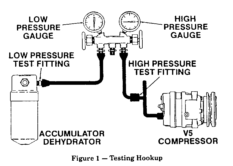
1. Connect manifold gauge set (Figure 1) to system high and low gauge fittings. Check that refrigerant charge is 50 psi minimum before continuing quick check procedure.
2. If system has low or no charge, refer to service manual and:
a. Charge system with one can of R12 refrigerant. b. Leak test system. c. Repair leaks. d. Evacuate and charge system with recommended amount of refrigerant. e. Leak test system.
D. CHECK ELECTRICAL SYSTEM FOR CLUTCH ENGAGEMENT: Engine Running At Idle
1. Set A/C controls to NORMAL, FULL COLD, and HIGH blower speed.
2. Check that clutch engages. If clutch does not engage, disconnect clutch terminal wire connector and temporarily wire directly to battery.
a. If clutch engages with direct wiring, problem is electrical. Perform service manual electrical diagnosis.
b. If clutch does not engage with direct wiring, replace clutch coil assembly per Section 1B of service manual.
E. CHECK REFRIGERANT SYSTEM PERFORMANCE: Engine Off To Start
IMPORTANT: Follow this procedure exactly. It is designed to create enough cooling load to cause the V5 Compressor to go to full stroke which is absolutely necessary for accurate test results. The following test was designed for typical garage conditions - 21 DEG - 32 degrees Celcius (70-90 degrees Fahrenheit), no sun load. Discharge air temperatures should be at least 11 degrees Celcius (20 degrees Fahrenheit) cooler than the outside ambient temperature.
1. Connect gauge set (Figure 1) to high and low A/C service fittings.
a. Some J Car and L Car applications require removal of the in-line pressure switch to read discharge pressure.
b. On some J Car applications the high side fitting is after the orifice tube and reads suction pressure instead of discharge pressure.
2. Check gauge set accuracy by reading both gauges; readings should be equal. Correct gauges as necessary.
3. Set high load test conditions:
a. Start engine and run at idle speed.
b. Open hood, close windows and doors.
c. Set A/C controls to HIGH blower and NORMAL cooling.
d. Run engine for five minutes.
4. Record and evaluate test results:
a. Record suction and discharge pressures. On systems having condenser fans that cycle on and off, pressure readings should be made when the fan is on.
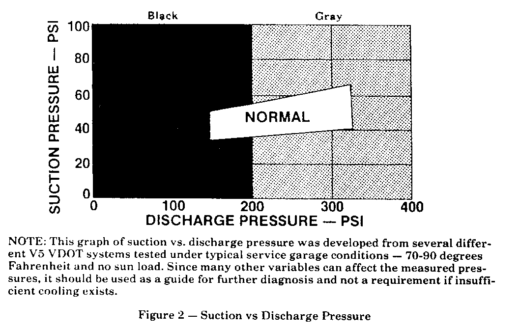
b. Check diagnostic test chart (Figure 2) and locate intersection of recorded suction and discharge pressures. Determine colour of area in which the pressures intersect (white, gray, or black).
c. Go to the proper colour heading for Diagnosis and Service Procedures. Diagnose in the sequence given to minimize time and expense of repair. Service tips are given with each diagnosis.
F. DIAGNOSIS AND SERVICE PROCEDURES
1. WHITE AREA DIAGNOSIS AND SERVICE
White area diagnosis means that all components of the refrigerant system are functioning properly. If insufficient cooling exists, air handling system is at fault. Check for:
a. Temperature door setting. Make sure temperature control is set to full cold position. Check and adjust for proper closing.
2. GRAY AREA DIAGNOSIS AND SERVICE
Check the following if pressures intersect in the gray area:
a. Improper condenser operation. This can result from:
- Extremely high ambient humidity. - Insufficient air flow across the condenser. - Damaged or dirty condenser fins. - Defective cooling fan. - Improperly calibrated high pressure fan switch. - Faulty fan relay.
b. High side refrigerant restriction. Feel liquid line before expansion tube (orifice). If line feels cold, it indicates restriction in high side. Visually check for frost spot to locate restriction and repair as necessary.
c. Refrigerant system overcharged (high discharge and high suction pressures). See below.
d. Orifice tube blocked (low suction pressures). See below.
e. Air in system (high discharge and high suction pressures). See below.
Items c, d, and e above can be corrected by the same procedure:
- Discharge refrigerant system slowly using the low pressure fitting to prevent oil loss. - Check orifice tube for blockage. Clean or replace as required (small amount of metal chips may be normal). - Evacuate system to a vacuum (improper evacuation of system prior to recharge will cause air to remain in system). - Recharge system with proper amount of refrigerant. - Leak check system.
3. BLACK AREA DIAGNOSIS AND SERVICE
Check the following if pressures intersect in the black areas:
a. Compressor may be internally damaged. If suction and discharge pressures are equal and do not change when the A/C mode is turned on and off, the compressor may be internally damaged. Excess heat at the clutch surfaces or a free wheeling clutch driver are signs of internal compressor damage. When replacing the compressor, follow component replacement procedures to maintain the correct oil charge in the system. Failure to do so may cause excessive noise and early compressor failure.
b. Missing expansion tube (orifice). Feel liquid line after expansion tube. If line is warm, discharge system and inspect for presence of expansion tube. If expansion tube or o-ring is missing, install new one in system. If expansion tube is present, remove, clean, or replace tube as necessary and install in system. Evacuate and charge system.
c. Compressor at minimum stroke. If compressor discharge pressure remains only 10-30 psi above suction pressure, compressor may be at minimum stroke. When noted, run engine at approximately 3000 rpm for three minutes until pressures become normal. During this period, cycle mode lever from vent to A/C every 20 seconds. If no change, perform control valve low load test.
d. Compressor control valve set improperly. Run low load test to verify. Follow this procedure exactly. It is designed to create a low cooling load causing the V5 compressor to go toward minimum stroke which is absolutely necessary for evaluation of control valve set point.
- Connect gauge set (Figure 1) to high and low A/C Service fittings. - Check gauge accuracy by reading both gauges. Correct gauges as necessary. - Disconnect blower motor. - Set test conditions: 1. Start engine and run at fast idle speed. 2. Open hood, close windows and doors. 3. Set A/C controls to LOW blower and MAX cooling. - Record and evaluate test results: 1. If suction pressure is 25-35 psi, control valve is functioning properly. 2. If suction pressure is outside limits of 25-35 psi, replace control valve.
e. Refrigerant system undercharged. This condition may exist when suction pressure is below 35 psi during the high load test. The accumulator (A/D) and the suction line before the A/D, will be warm if charge is low. Add one can of refrigerant and recheck. Pressures should come into white area. If so,find source of refrigerant loss and repair leak. Evacuate and charge system with correct refrigerant amount.
f. Expansion Tube (orifice) Blocked. See Step e in Grey Area Diagnosis and Service.


General Motors bulletins are intended for use by professional technicians, not a "do-it-yourselfer". They are written to inform those technicians of conditions that may occur on some vehicles, or to provide information that could assist in the proper service of a vehicle. Properly trained technicians have the equipment, tools, safety instructions and know-how to do a job properly and safely. If a condition is described, do not assume that the bulletin applies to your vehicle, or that your vehicle will have that condition. See a General Motors dealer servicing your brand of General Motors vehicle for information on whether your vehicle may benefit from the information.
