FRONT WHEEL DRIVE M/T REVISED SERVICE INFORMATION

"Please discard previous bulletin 83-T-49, Section 7, titled Servicing Front Wheel Drive Manual Transaxle - 1980-1983 Phoenix and 1982-1983 2000 Models ".
Pontiac has offered manual four speed front wheel drive manual transaxle in its Phoenix since 1980, on its 2000 since 1982 and in 1984 on the Fiero. This bulletin upgrades existing information on these units. Areas covered are: (1) shift effort and feel, (2) worn shifter forks, and (3) gear noise.
1. SHIFT EFFORT AND SHIFT QUALITY
A. First check to be sure no assembly aids are left on car.
In car: 5/32" pin - locks shifting lever mechanism in first gear.
"Yoke clip" holds shifter in 1-2 gate, no reverse or 3-4 shift is possible.
Underhood: Inspect shifter shaft below shift lever to see that no biasing clip (large hairpin) is present.
B. If car is new, shift feel may be improved by shifting through the gears many times (25-50), which conditions the transaxle.
C. Next perform the following adjustment - two (2) man procedure.
1. Disconnect battery cable.
2. From inside car, shift into first gear and hold in position all the way forward and to the left as far as it will go.
3. Underhood, loosen nuts on selector lever and shift lever.
4. Underhood, remove lash in select lever (top lever) by pushing it toward driver side of car (clockwise) and holding it while nut is tightened.
DO NOT USE POWER TOOLS
5. Repeat Step 4 for shift lever, removing lash in same manner and tighten nut. Check for equal overshift in first and second gear, if not equal, readjust until overhsift is equal.
6. Recheck adjustment by shifting transmsision from inside car while observing motion of both shift levers underhood. Little or no movement of select lever should be noted on 1-2 or 3-4 shift. If excessive movement of select lever is noted, repeat entire adjustment procedure (Steps 2-6) before proceeding.
7. Drive car and evaluate improvement.
BEFORE REMOVING TRANSAXLE, VERIFY SHIFT PROBLEM IS INTERNAL TO GEAR BOX
1. Disconnect cables at select and shift levers.
2. Check shifter and cables for freedom of operation. Repair as necessary.
3. Manually shift transaxle with select and shift levers to check for ease of operation and verify problem is in transaxle.
With transaxle removed, inspect shift forks for wear. If shift fork is worn or binds, replace both shifter fork and synchronizer.
When reassembling transaxle, use shimming procedure provided in II, D.
II. GEAR NOISE
Resolving a transaxle gear noise or whine complaint begins with a good diagnosis to determine if the noise is related:
to the transaxle at all.
to the noise paths into the passenger compartments.
to the parts of assembly of the transaxle.
A. Is it transaxle noise at all?
Other noises are sometimes mistaken for gear noise especially higher pitched airborne noises such as wind whistle, grill noise, tire noise, etc. Transaxle gear noise will be throttle and car speed sensitive; i.e., gear noise will increase in pitch as speed increases.
NOTICE: 1st and 2nd gear noise:
- Don't be too critical, as they are not "cruising gears". - 3rd and 4th gear noise. - You must differentiate between 3rd/4th gearset noises and final drive gearset noises before removing transmission from car.
To determine if it is final drive gear noise or speed gear noise, drive the car at a constant speed and shift between 3rd and 4th gear. If the pitch of noise stays the same, it is final drive gear noise. If the pitch changes drastically, it is speed gear noise.
NOTICE: Recognize that determination is difficult. Final drive noise is most comon with 3:31 final drive ratio.
B. Check routes for noise into passenger compartment.
Because the gears in the transaxle are in mesh, some noise or whine will be generated with perfect gears. Noise isolation built into the car eliminates most of this "normal" noise intrusion into the passenger compartment. Once the gear noise has been determined to be authentically from the transaxle, the following noise isolation items should be checked before transaxle removal.
1. Shift Cable Installation - make sure cables are snapped squarely into the shifter and grommet is snapped firmly into place in dash.
2. Shift Cable Routing - Cables should be free from kinks, sharp bends and "grounding out" against other components. The carpet should not cause any kinks or binds in the cables.
3. Dash Insulation - should be checked to make sure all "holes" are sealed.
C. Transaxle gear replacement.
If the noise persists after checking routes for noise into passenger compartment, then the transaxle should be removed to remedy:
poor machining of gears.
improper shiming (preload).
D. Shiming procedure (preload).
It is essential that the following new shimming procedure be used in reassembly of the transaxle (same as 1982 Service Manual except Step 7, which is revised). The complete procedure follows.
Selection of the preload shims for reassembly can begin when the input and output shaft assemblies and the differential assembly are reassembled and ready to be installed into the transaxle case.
1. Place the transaxle case into holding fixture J-28408.
2. With the three (3) L.H. bearing races installed in the case, place the input and output shaft assemblies and the differential assembly into their installed positions.
Place the three (3) R.H. bearing races onto their respective bearings.
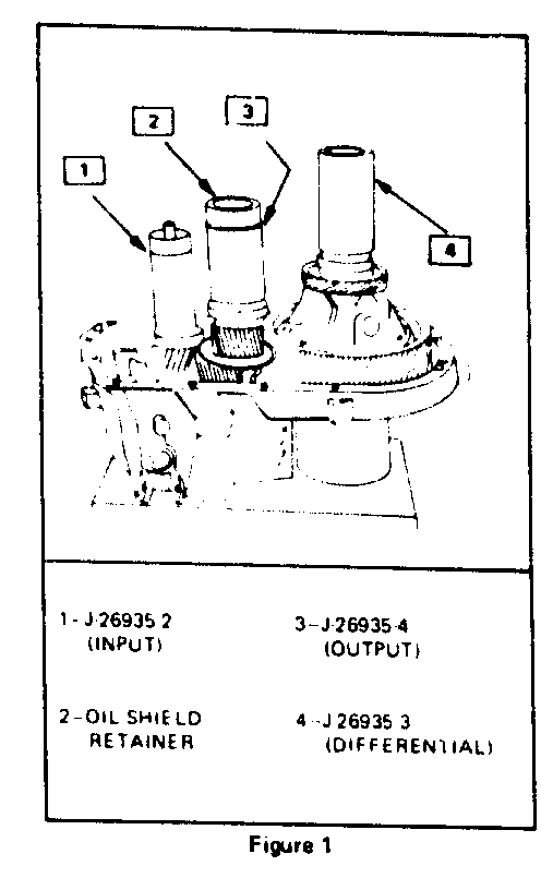
3. Position three (3) gages; J-26935-2 on input bearing and J-26935-4 onto output bearing and J-26935-3 on the differential bearing. Be sure the bearing races fit smoothly into the bores of the gage tools (see Figure 1).
4. On J-26935-4 (output shaft), install metal oil shield retainer into bore on top of tool.
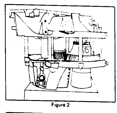
5. Carefully assemble the clutch cover over the three (3) gages and onto the case, using seven (7) (see Figure 2). Draw the cover to the case by tightening alternately and gradually. Torque bolts to 10 ft. lbs. (13 N.m). This will compress all three (3) gage sleeves.
6. Rotate each gage to seat the bearings. Rotate the differential case through three (3) revolutions in each direction.
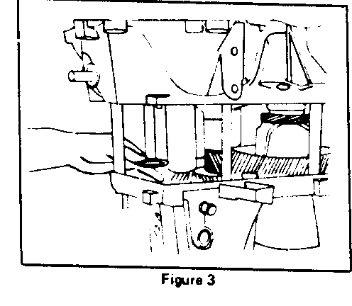
7. With the three (3) gages compressed, the gap between the outer sleeve and the base pad is larger than the correct preload shim at each location. Carefully compare the gap to the available shims. Determine the largest shim that can be placed into differential gap and drawn through without binding. Use the next size smaller shim for this location. Repeat procedure to select output shaft shim. On the input shaft, repeat this procedure and use a shim two (2) sizes smaller than the largest shim that can be drawn through without binding (Figure 3).
8. When each of the three (3) shims has been selected, remove the clutch cover, spacers (7) and gages (3).
9. Place the selected shims into their respective bores in the clutch cover, add the metal shield and then install the bearing cups using special tool J-26936 on input shaft and J-23423-A on output shaft cup and J-26938 on the differential side bearing cup.
10. After assembly, check end play of input shaft. If any end play is present, replace shim with next size larger at this location.
11. Reinstall transaxle in car and perform shift cable adjustment as outlined previously.


General Motors bulletins are intended for use by professional technicians, not a "do-it-yourselfer". They are written to inform those technicians of conditions that may occur on some vehicles, or to provide information that could assist in the proper service of a vehicle. Properly trained technicians have the equipment, tools, safety instructions and know-how to do a job properly and safely. If a condition is described, do not assume that the bulletin applies to your vehicle, or that your vehicle will have that condition. See a General Motors dealer servicing your brand of General Motors vehicle for information on whether your vehicle may benefit from the information.
