GM Service Manual Online
For 1990-2009 cars only
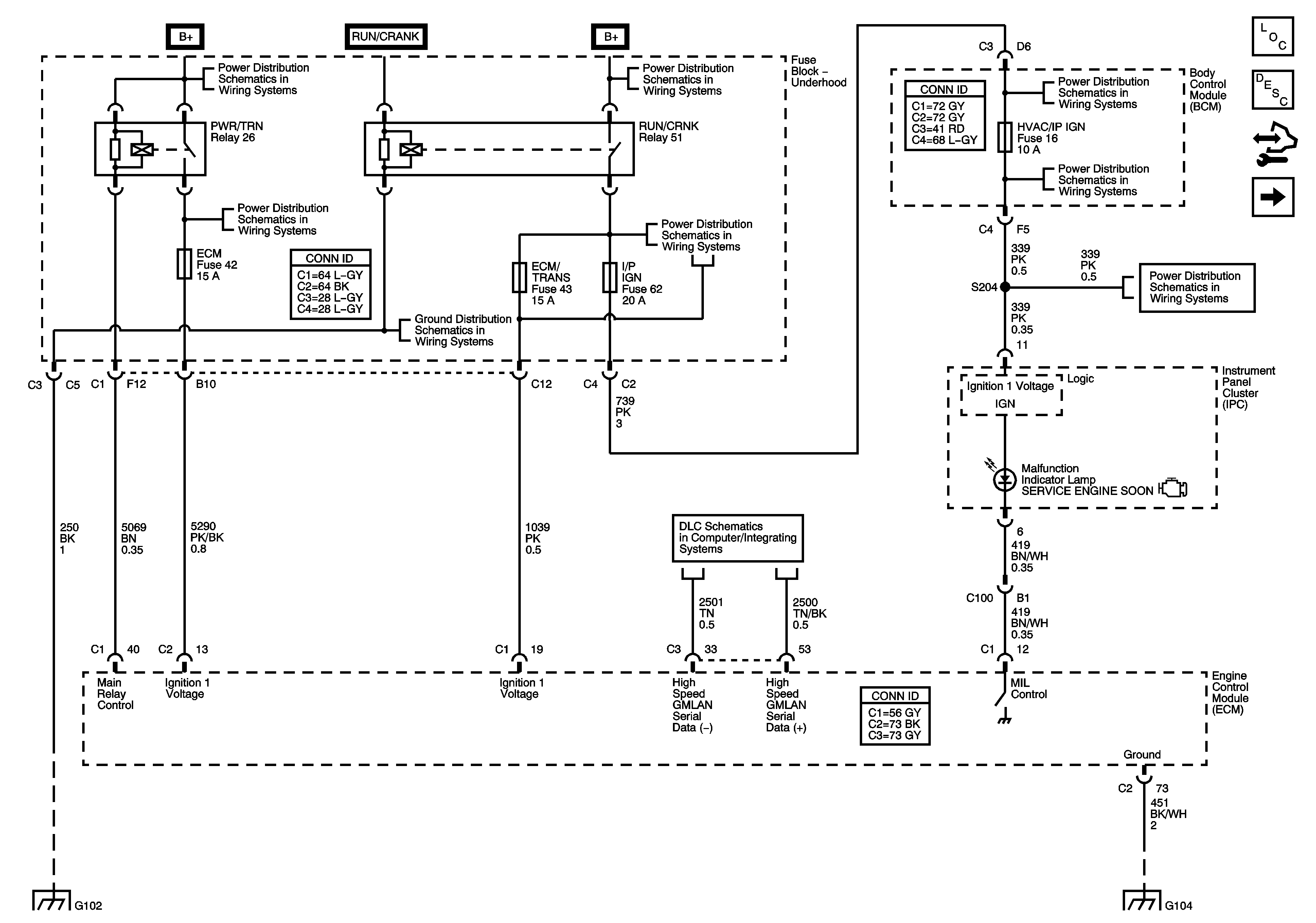
Figure 1:

Module, Power, Ground, Serial Data, and MIL

Object Number: 1575818  Size: FS
Master Electrical Component List
Engine Control Module Description
Control Module References
Engine Data Sensors - 5-Volt and Low Reference
B+ Bus Bar - 1 of 2
B+ Bus Bar - 1 of 2
B+ Bus Bar - 1 of 2
B+ Bus Bar - 1 of 2
AIR BAG, AMP, BCM 2, BCM 3, CLSTR, EPS/STR WHL CNTRL, HVAC/IP IGN, HVAC/PK3+, and WPR Fuses
High Speed GMLAN
G103, G204, G105, G104, and G106
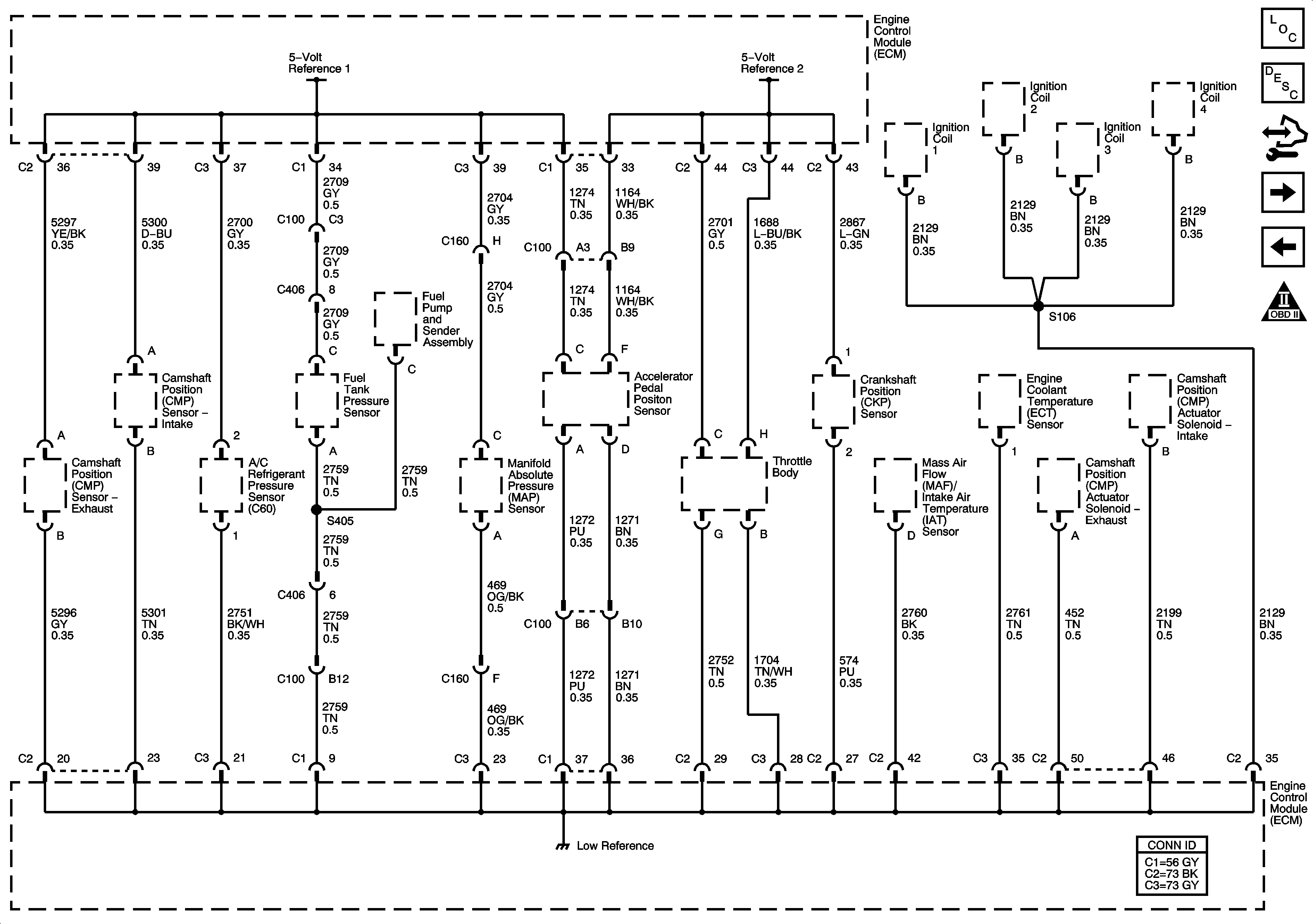
Figure 2:

Engine Data Sensors - 5-Volt and Low Reference


Object Number: 1575819  Size: FS
Master Electrical Component List
Engine Control Module Description
Control Module References
Engine Data Sensors - Pressure and Temperature
Module Power, Ground, Serial Data, and MIL
Engine Controls Schematic Icons
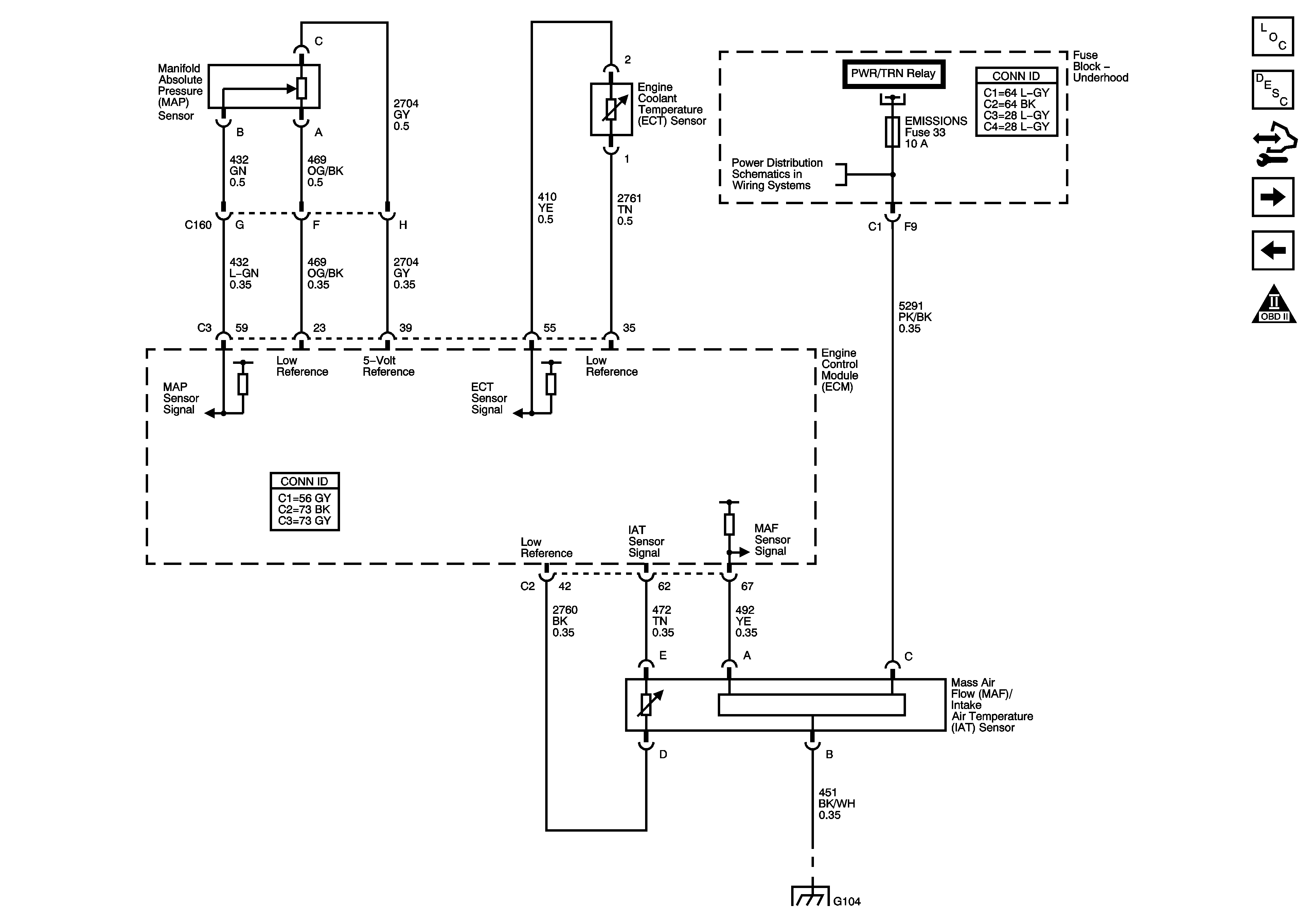
Figure 3:

Engine Data Sensors - Pressure and Temperature


Object Number: 1575821  Size: FS
Master Electrical Component List
Engine Control Module Description
Control Module References
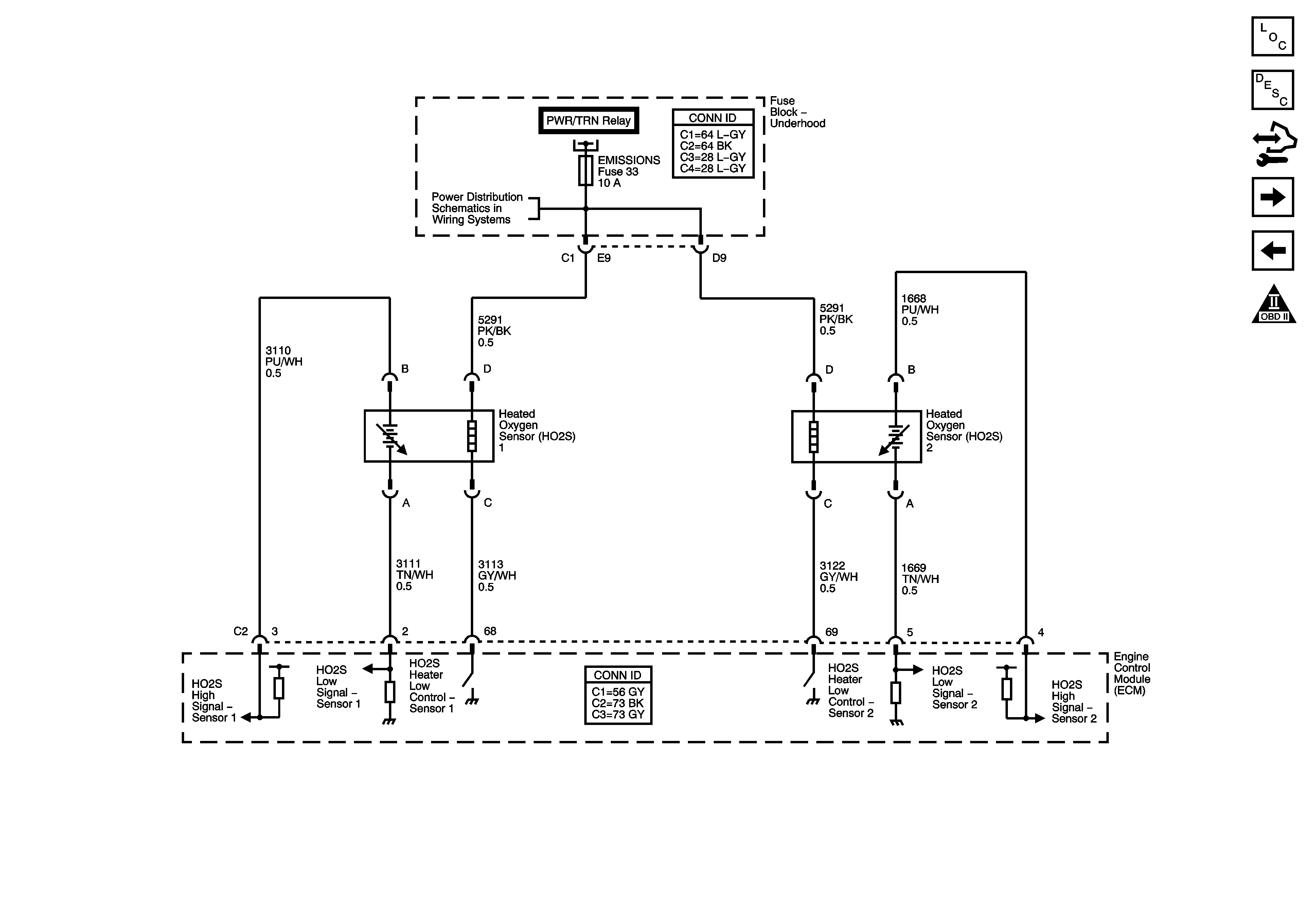
Engine Data Sensors - Oxygen Sensors
Engine Data Sensors - 5-Volt and Low Reference
Engine Controls Schematic Icons
B+ Bus Bar - 1 of 2
G103, G204, G105, G104, and G106
Figure 4:

Engine Data Sensors - Oxygen Sensors


Object Number: 1575822  Size: FS
Master Electrical Component List
Engine Control Module Description
Control Module References
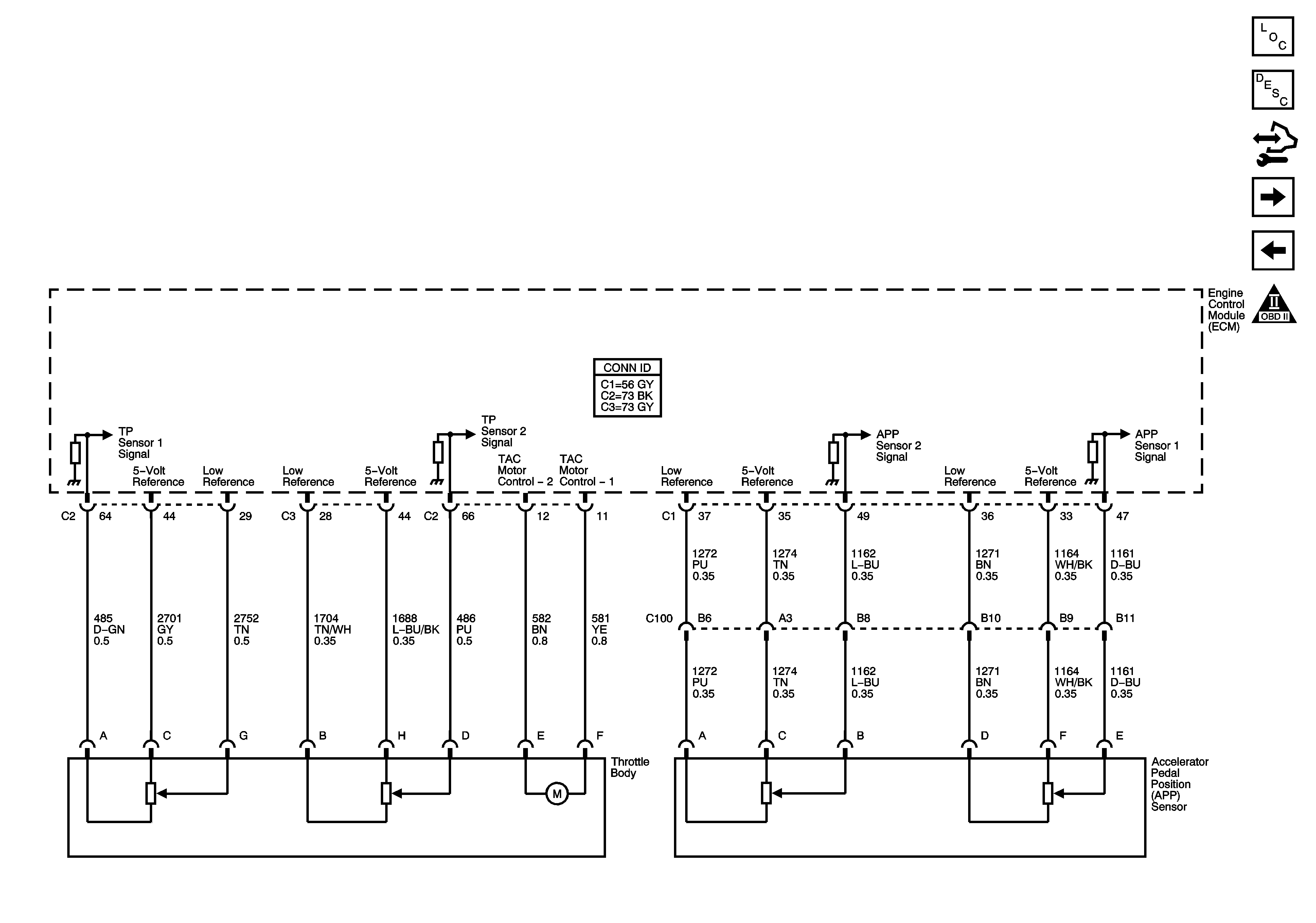
Engine Data Sensor - Pedal Position
Engine Data Sensors - Pressure and Temperature
Engine Controls Schematic Icons
B+ Bus Bar - 1 of 2
Figure 5:

Engine Data Sensors - Pedal Position


Object Number: 1575824  Size: FS
Master Electrical Component List
Engine Control Module Description
Control Module References
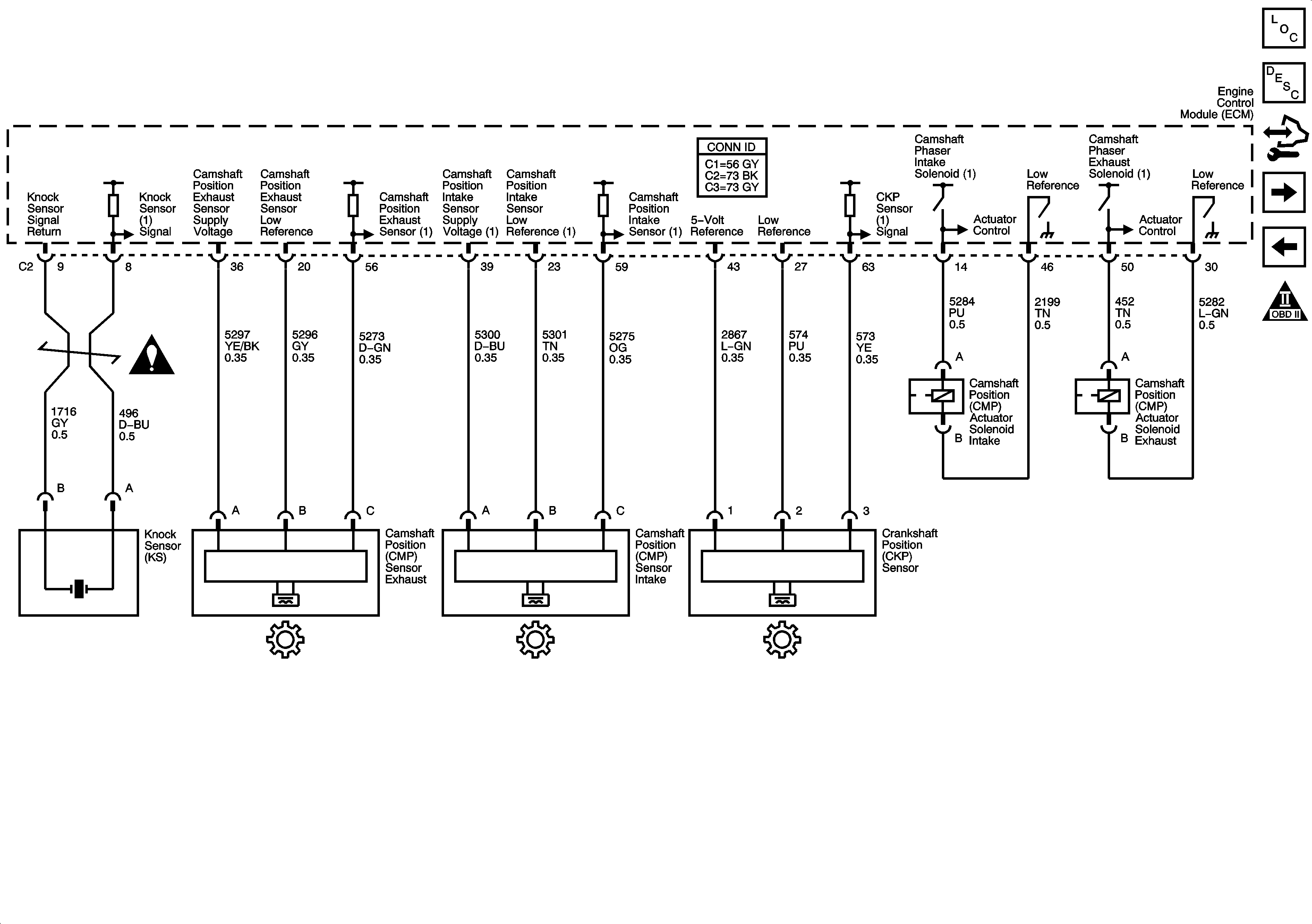
Ignition Controls - Semsors
Engine Data Sensors - Oxygen Sensors
Engine Controls Schematic Icons
Figure 6:

Ignition Controls - Sensors


Object Number: 1575825  Size: FS
Master Electrical Component List
Electronic Ignition (EI) System Description
Control Module References
Fuel Controls - Fuel Pump Controls and Fuel Injectors
Engine Data Sensor - Pedal Position
Engine Controls Schematic Icons
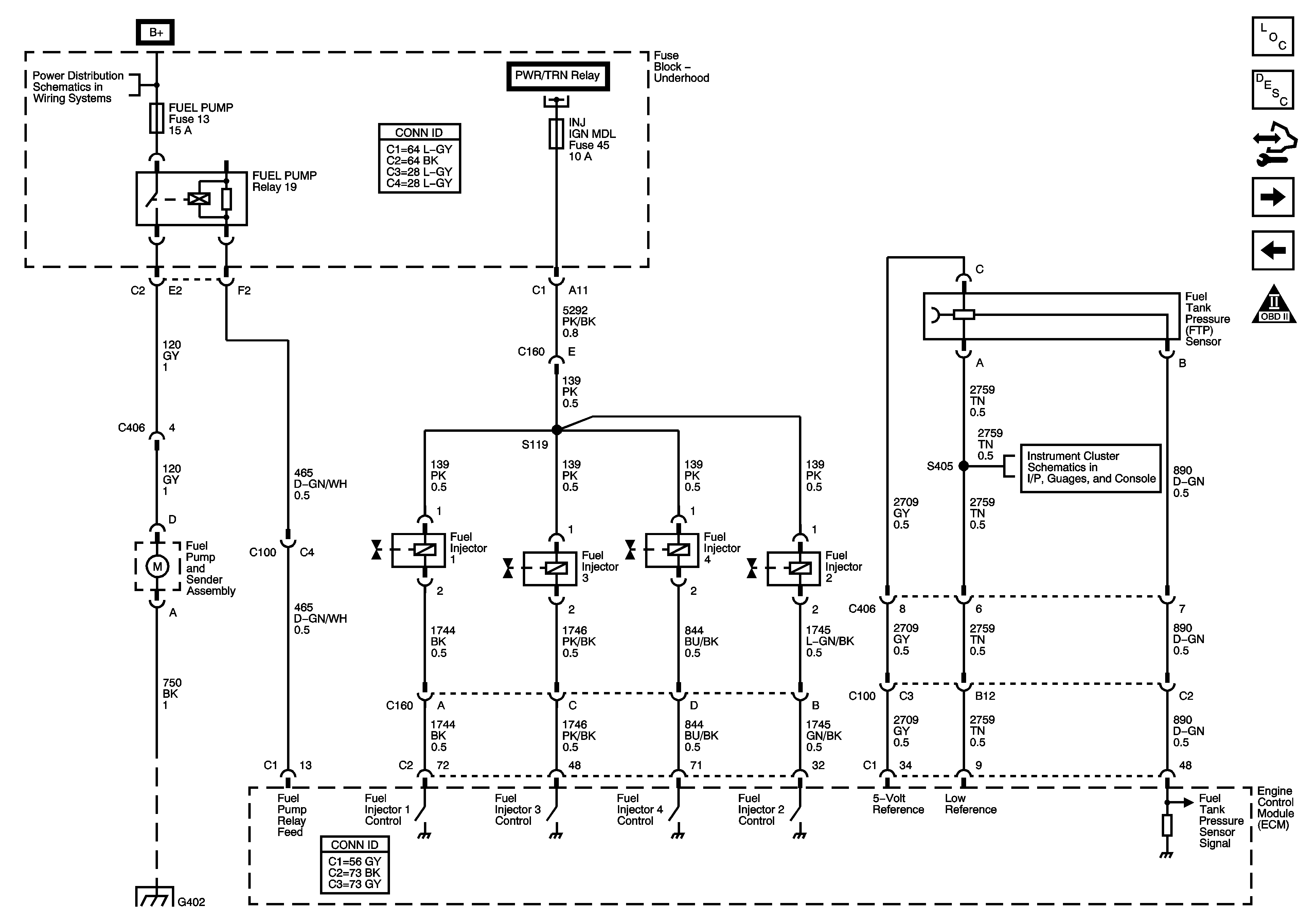
Figure 7:

Fuel Controls - Fuel Pump Controls and Fuel Injectors


Object Number: 1575827  Size: FS
Master Electrical Component List
Fuel System Description
Control Module References
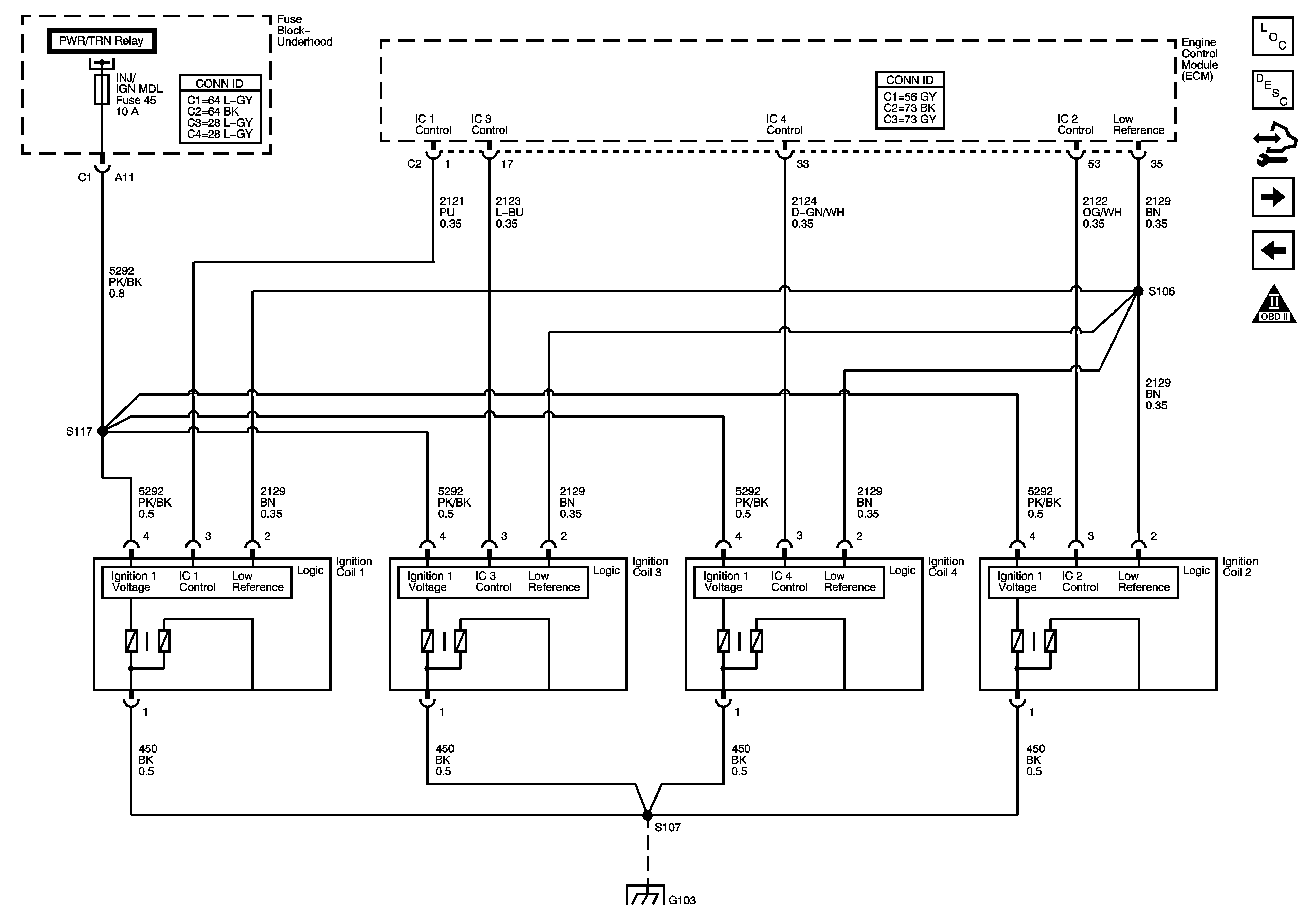
Ignition Controls - Ignition System
Ignition Controls - Semsors
Engine Controls Schematic Icons
B+ Bus Bar - 1 of 2
Instrument Cluster Schematics
G301, G102, G303, and G402
Figure 8:

Ignition Controls - Ignition System


Object Number: 1575829  Size: FS
Master Electrical Component List
Fuel System Description
Control Module References
Fuel Controls - EVAP Controls
Fuel Controls - Fuel Pump Controls and Fuel Injectors
Engine Controls Schematic Icons
B+ Bus Bar - 1 of 2
G103, G204, G105, G104, and G106
Figure 9:

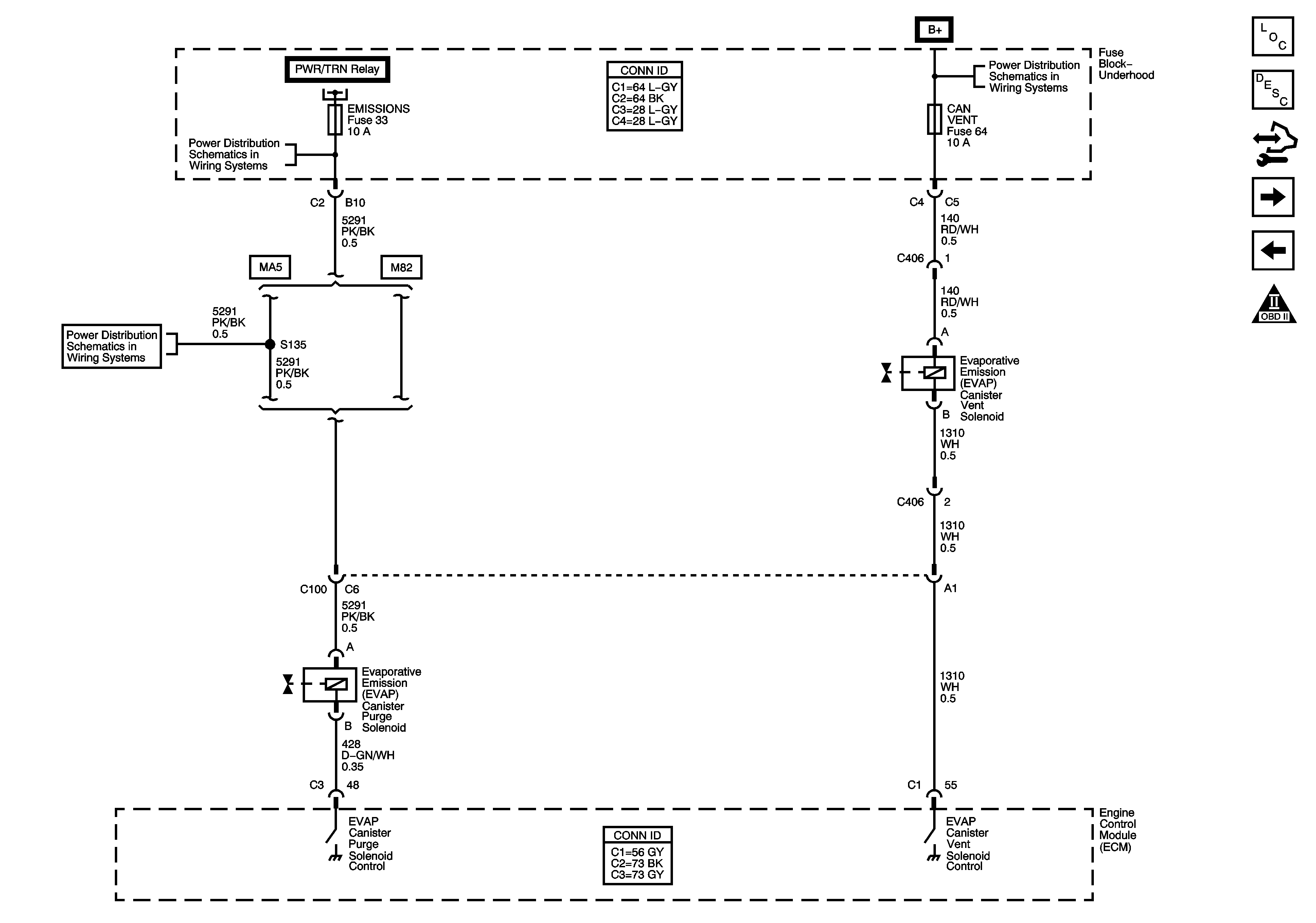
Fuel Controls - EVAP Controls


Object Number: 1575831  Size: FS
Master Electrical Component List
Fuel System Description
Control Module References
Controlled/Monitored Subsystem References
Ignition Controls - Ignition System
Engine Controls Schematic Icons
DLC, ECM, EMISSIONS, INJ IGN MDL, and LIGHTER Fuses
B+ Bus Bar - 1 of 2
B+ Bus Bar - 1 of 2
ABS 10A, BCK/UP, BCK/UP LAMP, CAN VENT, ECM/TRANS, I/P IGN, and TRUNK Fuses
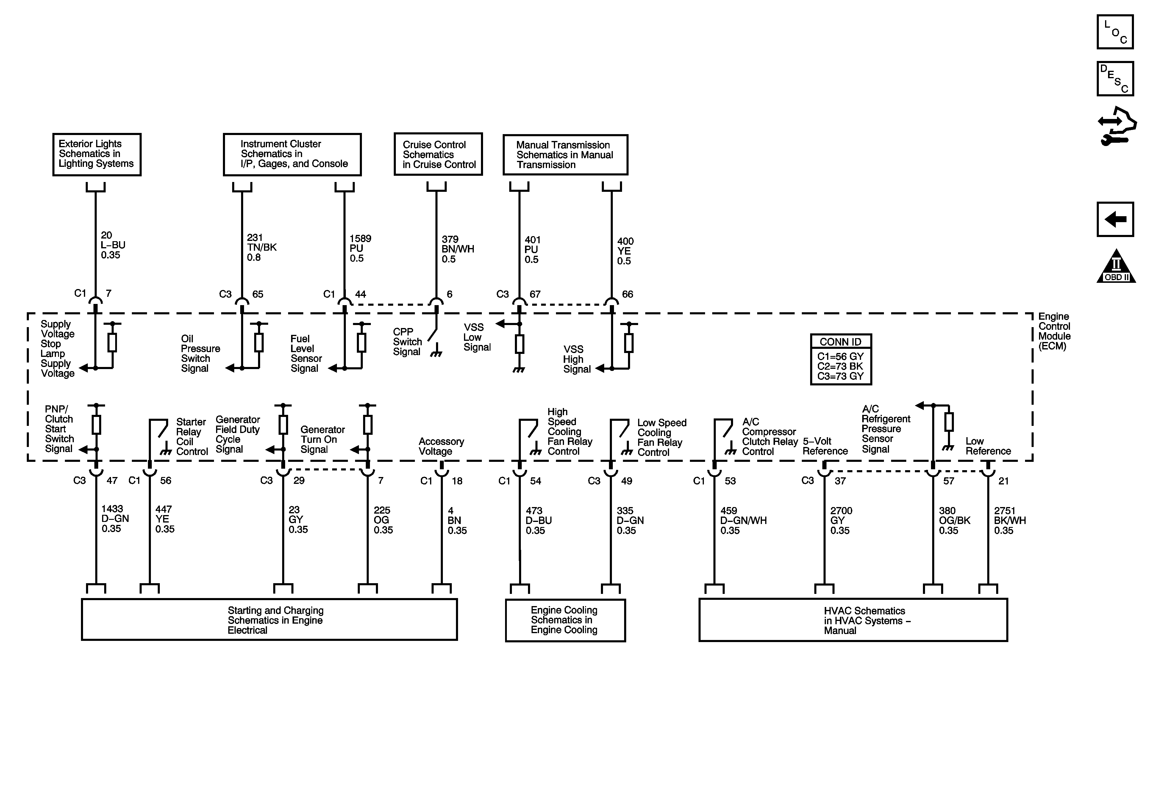
Figure 10:

Controlled/Monitored Subsystem References


Object Number: 1575832  Size: FS
Master Electrical Component List
Fuel System Description
Control Module References
Fuel Controls - EVAP Controls
Engine Controls Schematic Icons
Stop and Turn Signal Lamps
Instrument Cluster Schematics
Cruise Control Schematics
Manual Transmission Schematics
Engine Electrical Schematics
Engine Cooling Schematics
A/C Compressor Controls