GM Service Manual Online
For 1990-2009 cars only
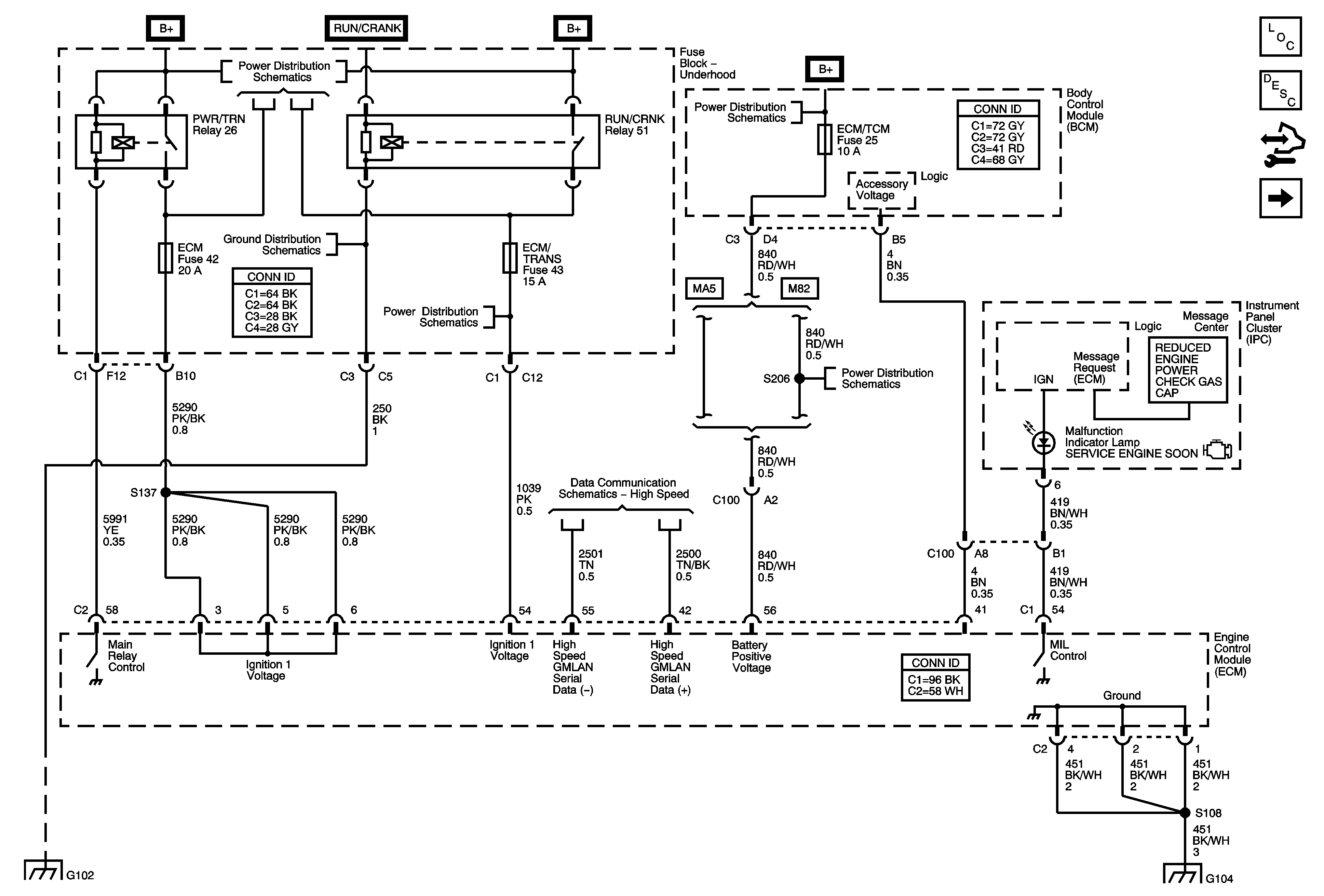
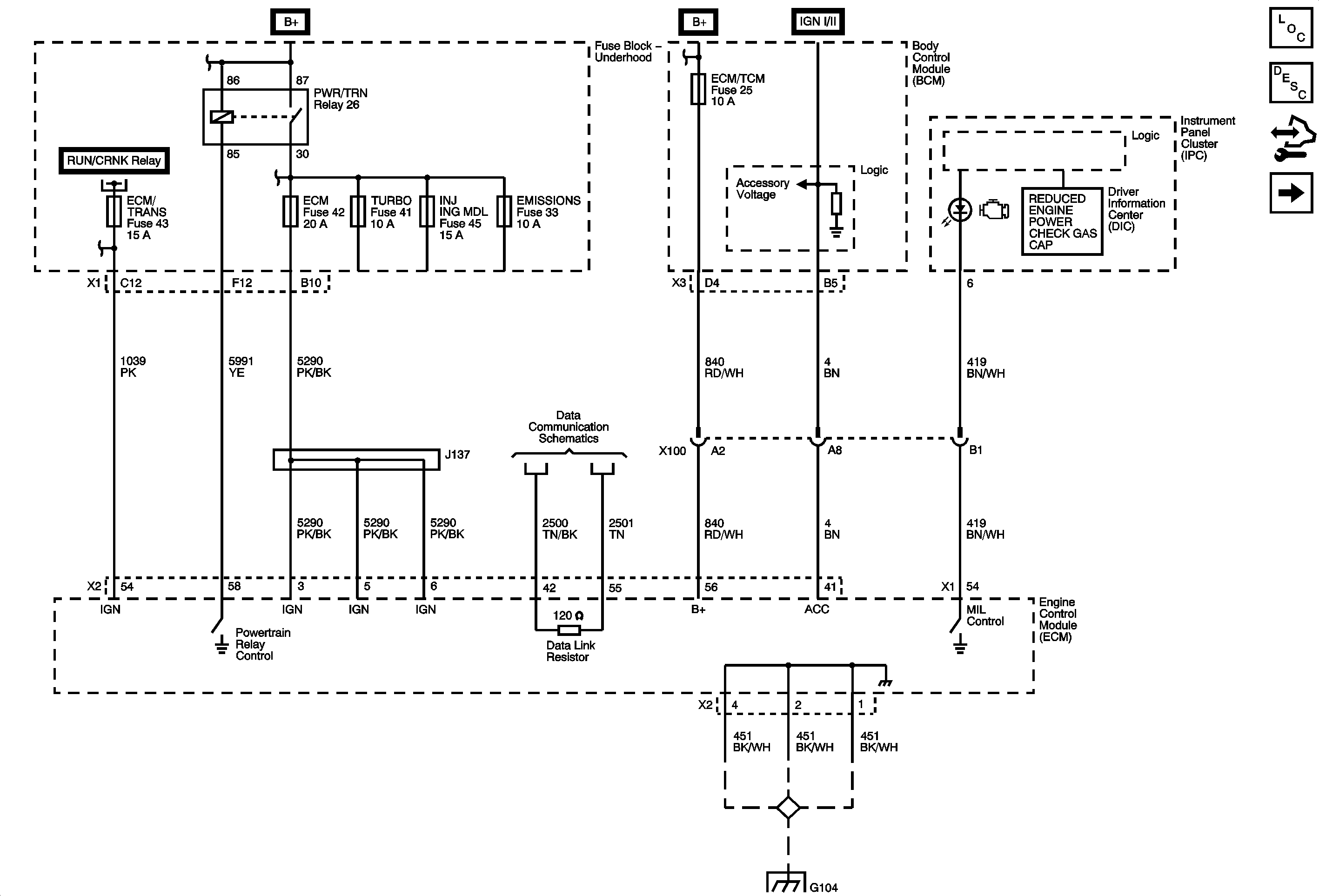
Figure 1:

Data Link, Ground, MIL, and Power


Object Number: 1829433  Size: FS
Master Electrical Component List
Engine Control Module Description
Control Module References
5-Volt and Low Reference
DLC, ECM, EMISSIONS, INJ IGN MDL, and TURBO Fuses, PWR/TRN Relay
BCM Fuse (Underhood Fuse Block), DR LCK, ECM/TCM, INT LIGHT, PWR WNDW, RDO, and SDM Fuses, DOOR LOCK PCB , DOOR UNLOCK PCB, DR DOOR UNLOCK PCB, INADVERTENT LOAD CONTROL PCB, and RAP Relays (BCM)
G101 and G102
ABS, BCK/UP LAMP, CAN VENT, ECM/TRANS, I/P IGN, and OUTLET Fuses, and RUN/CRNK Relay (Underhood Fuse Block), AIRBAG, EPS/STR WHL CNTRL, HVAC/IP IGN, and WPR Fuses (Body Control Module (BCM))
BCM Fuse (Underhood Fuse Block), DR LCK, ECM/TCM, INT LIGHT, PWR WNDW, RDO, and SDM Fuses, DOOR LOCK PCB , DOOR UNLOCK PCB, DR DOOR UNLOCK PCB, INADVERTENT LOAD CONTROL PCB, and RAP Relays (BCM)
High Speed LAN
G101 and G102
G103, G304, G105, G104, and G106
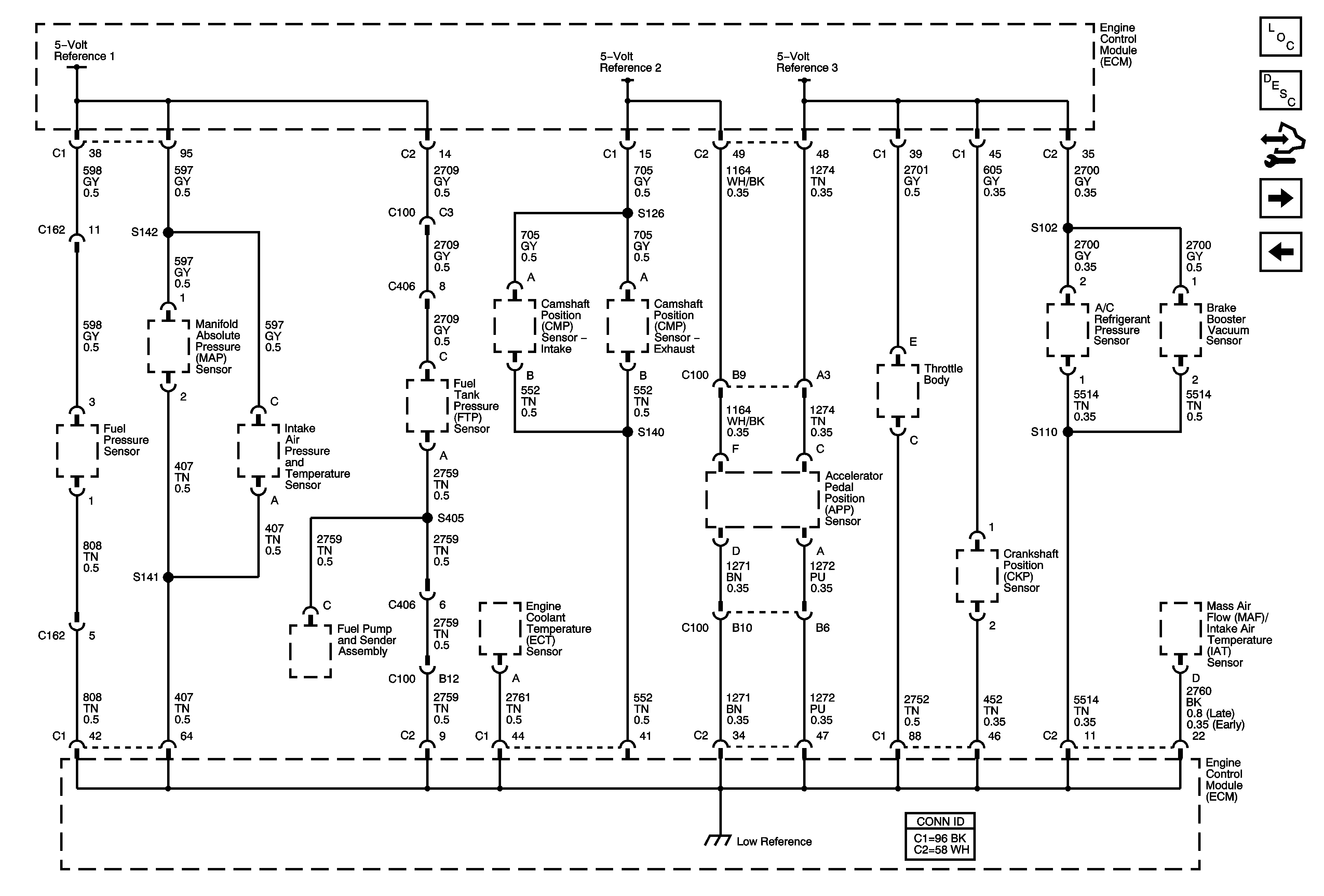
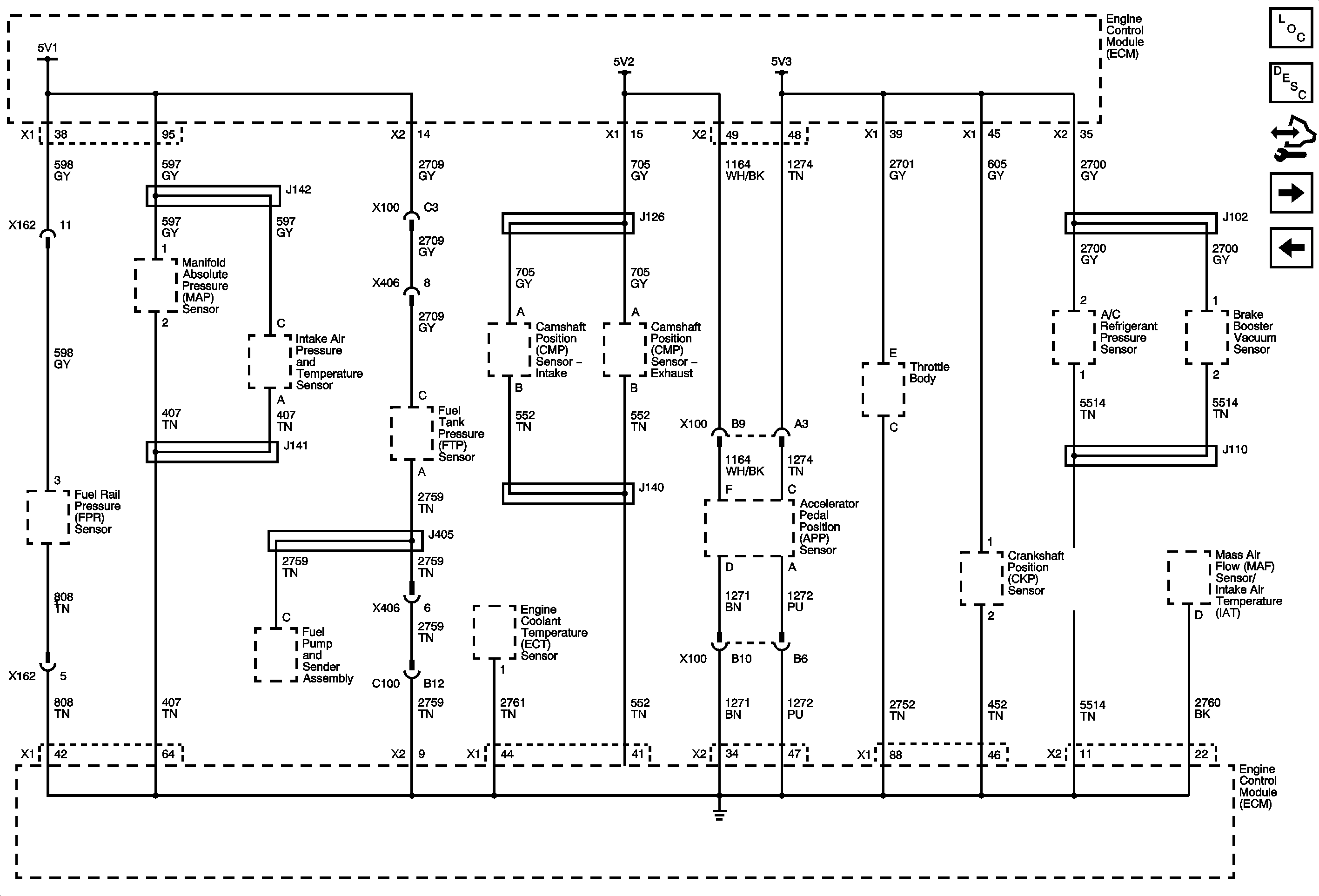
Figure 2:

5-Volt and Low Reference


Object Number: 1829436  Size: FS
Master Electrical Component List
Engine Control Module Description
Control Module References
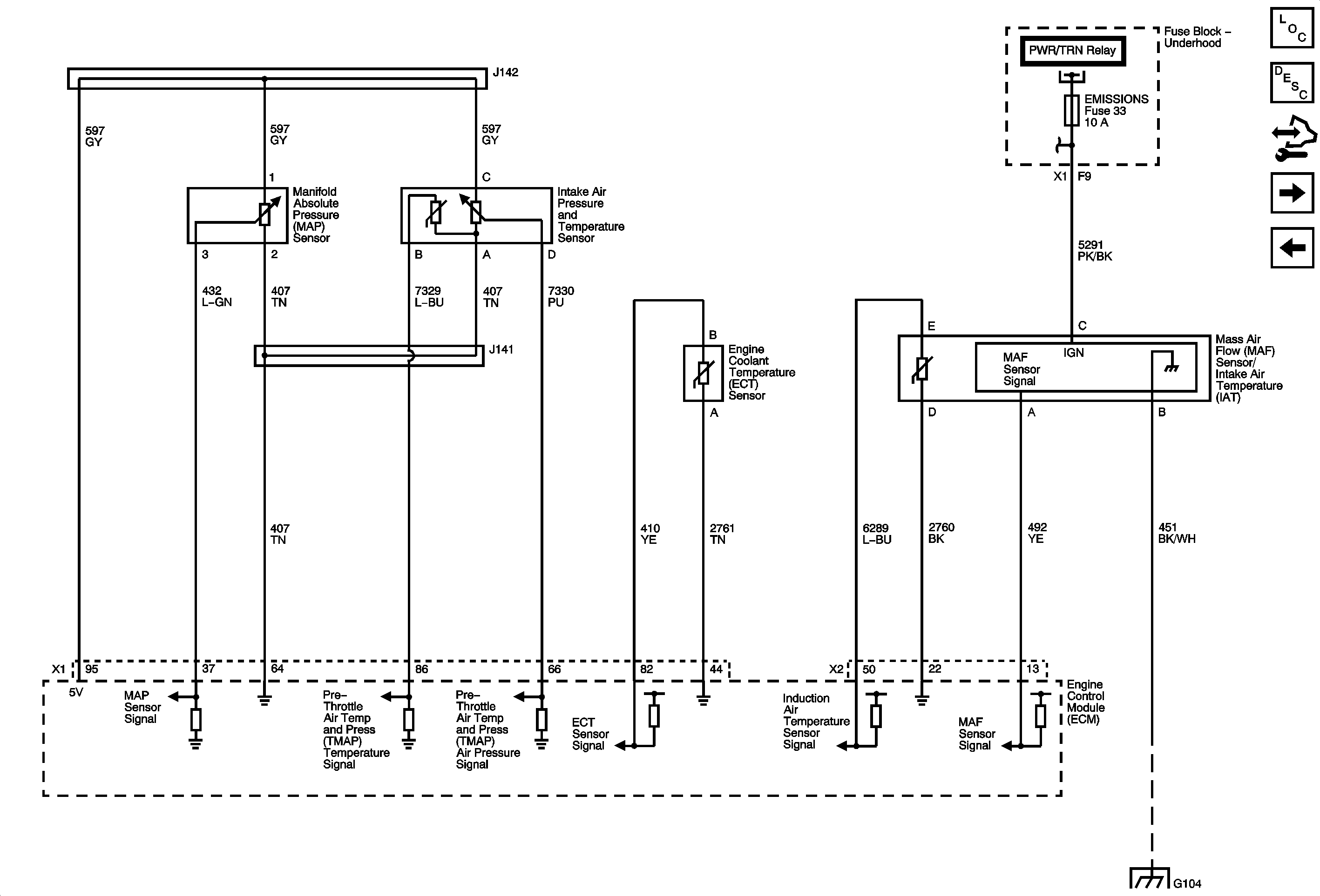
Engine Data Sensors - Pressure and Temperature
Data Link, Ground, MIL, and Power
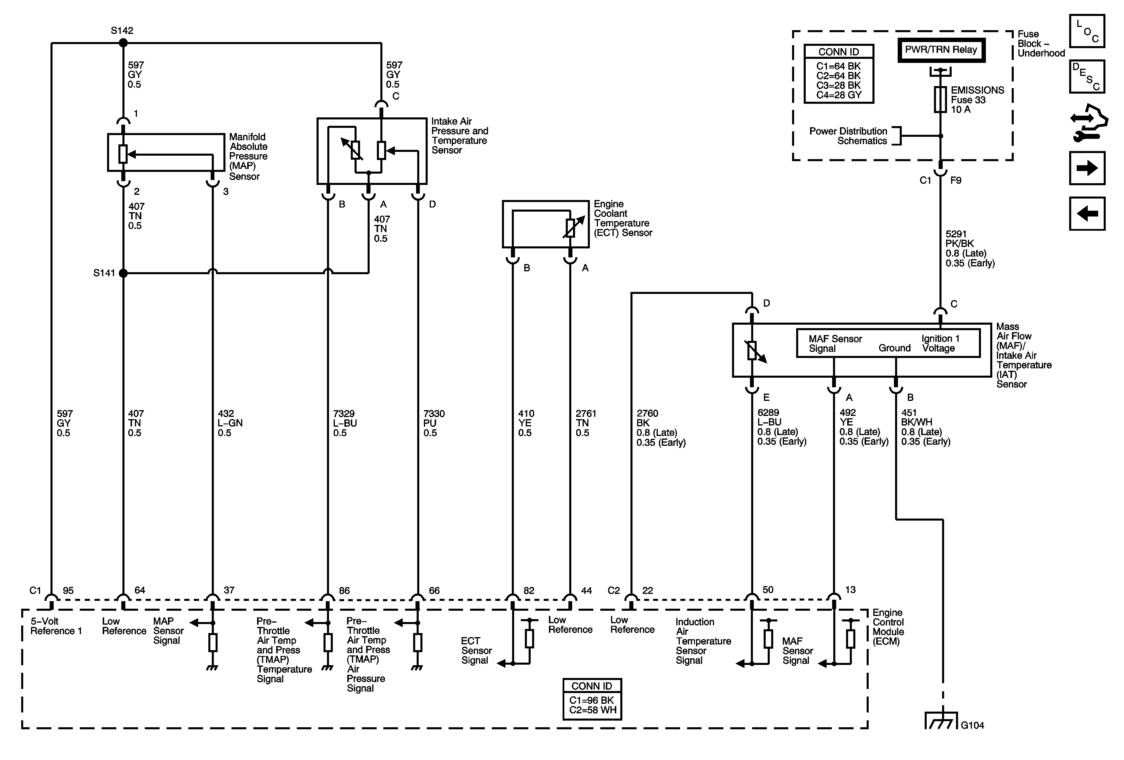
Figure 3:

Engine Data Sensors - Pressure and Temperature


Object Number: 1829490  Size: FS
Master Electrical Component List
Air Intake System Description
Control Module References
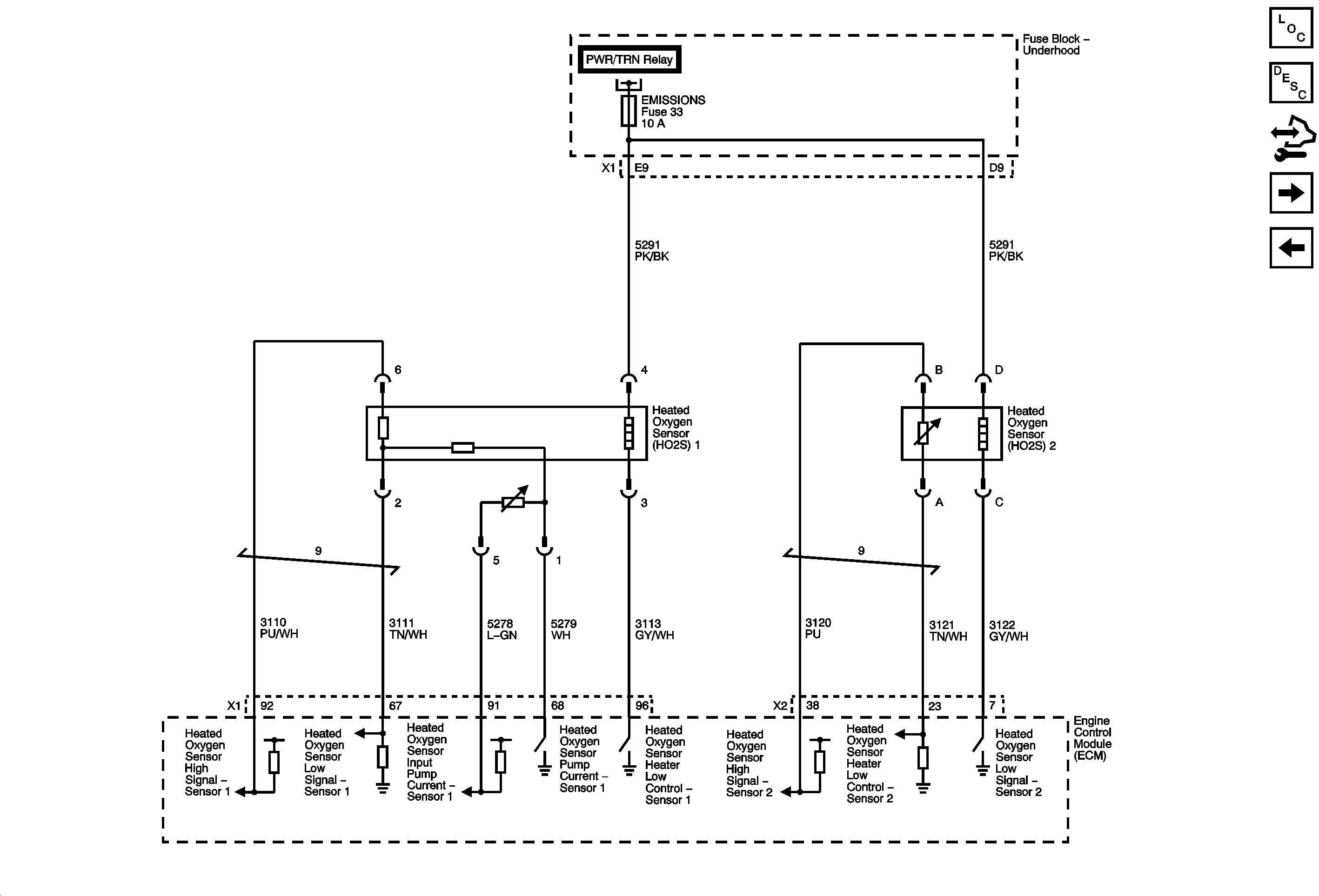
Engine Data Sensors - Oxygen Sensors
5-Volt and Low Reference
DLC, ECM, EMISSIONS, INJ IGN MDL, and TURBO Fuses, PWR/TRN Relay
G103, G304, G105, G104, and G106
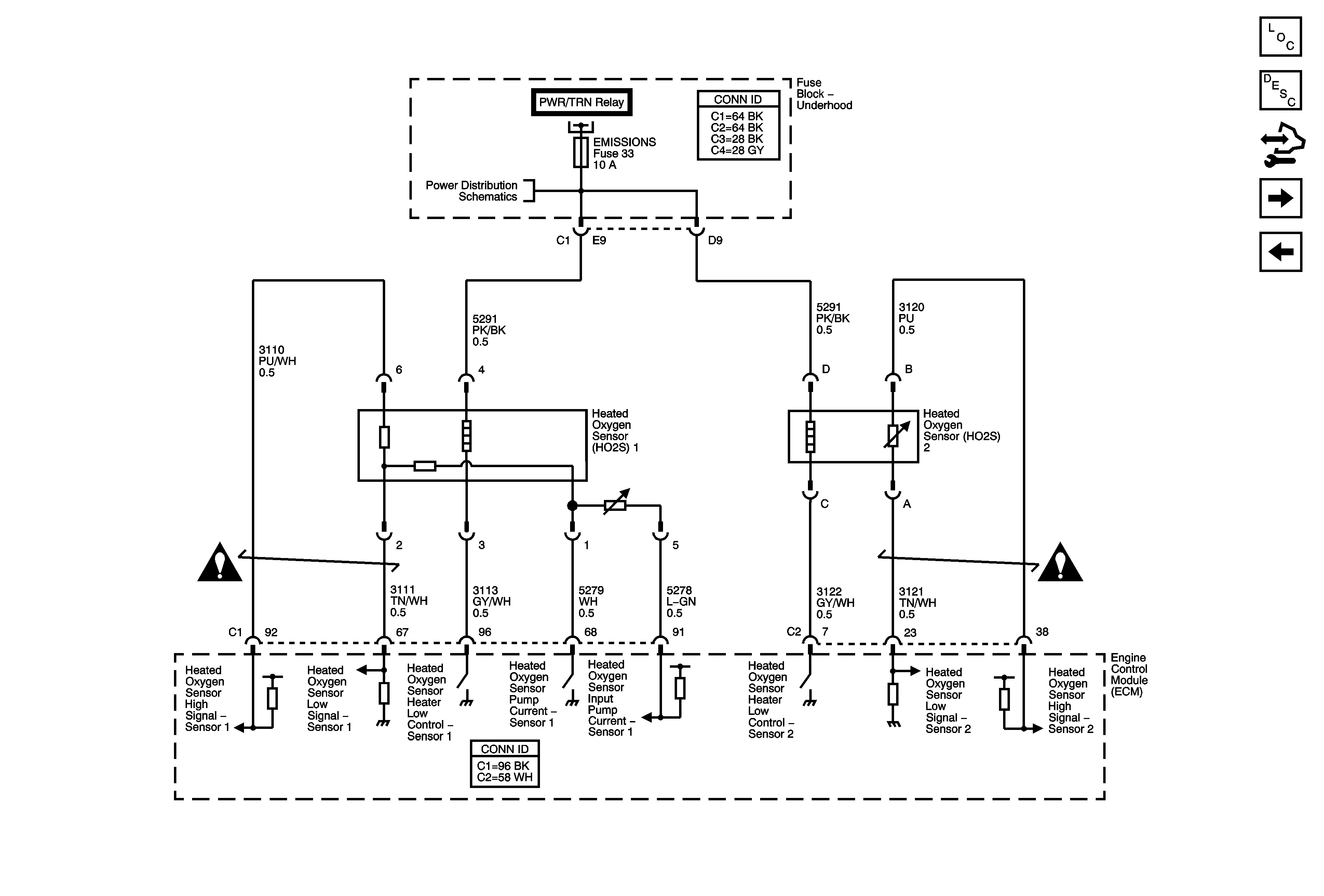
Figure 4:

Engine Data Sensors - Oxygen Sensors


Object Number: 1829493  Size: FS
Master Electrical Component List
Engine Control Module Description
Control Module References
Engine Data Sensors - Electronic Throttle Controls
Engine Data Sensors - Pressure and Temperature
DLC, ECM, EMISSIONS, INJ IGN MDL, and TURBO Fuses, PWR/TRN Relay
Engine Controls Schematic Icons
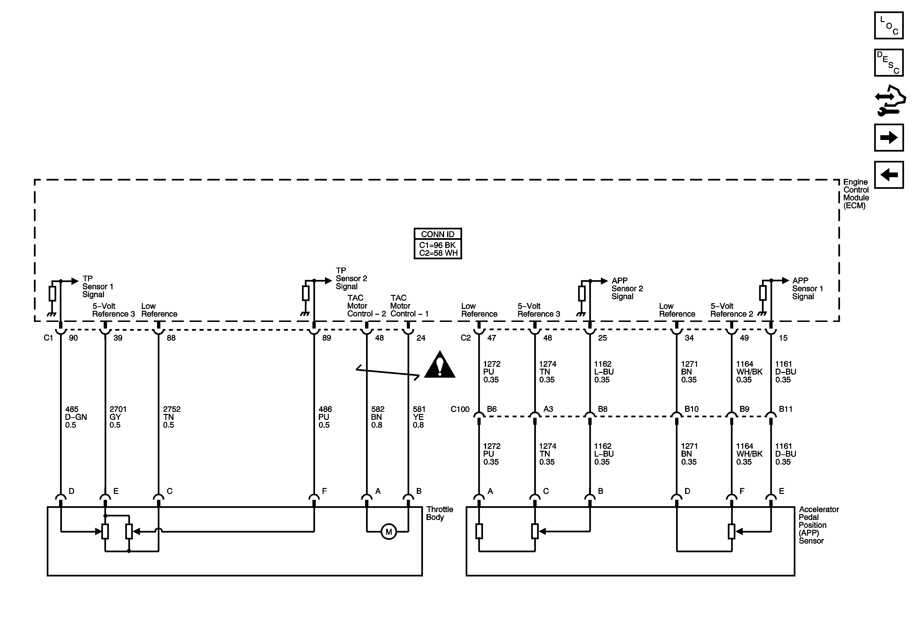
Figure 5:

Engine Data Sensors - Electronic Throttle Control

Object Number: 1829500  Size: FS
Master Electrical Component List
Throttle Actuator Control (TAC) System Description
Control Module References
Ignition Controls - Sensors
Engine Data Sensors - Oxygen Sensors
Engine Controls Schematic Icons
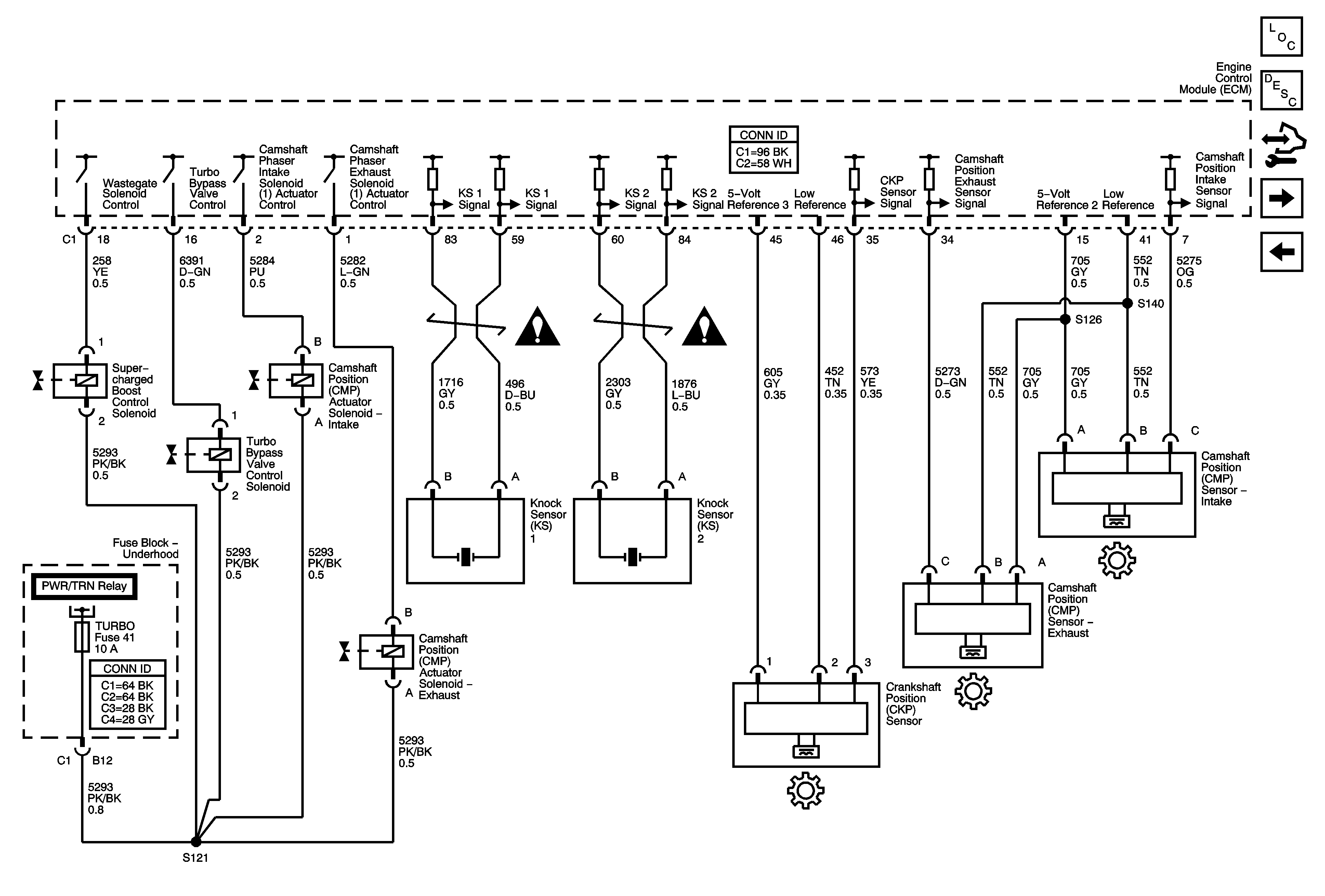
Figure 6:

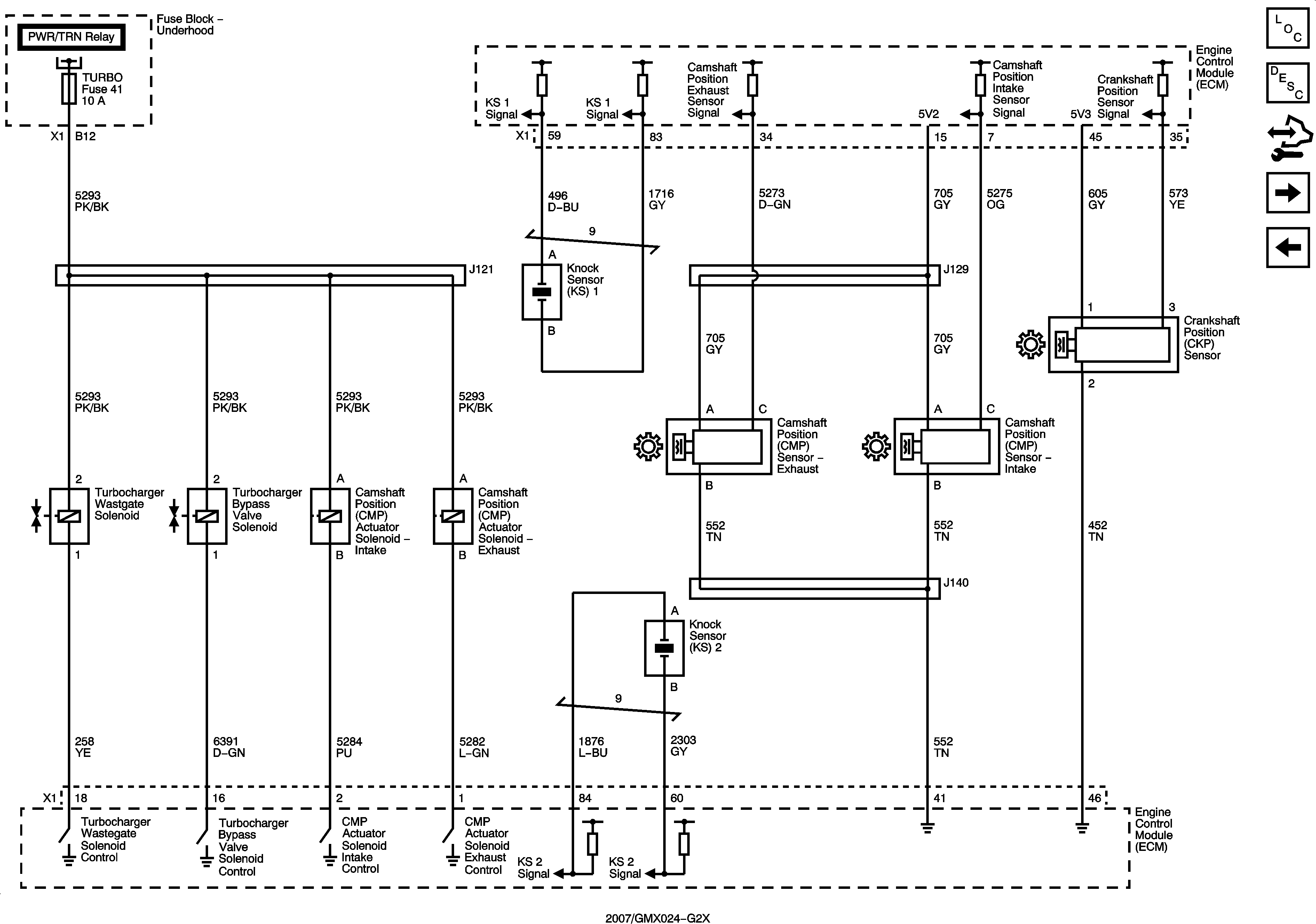
Ignition Controls - Sensors


Object Number: 1829502  Size: FS
Master Electrical Component List
Electronic Ignition (EI) System Description
Control Module References
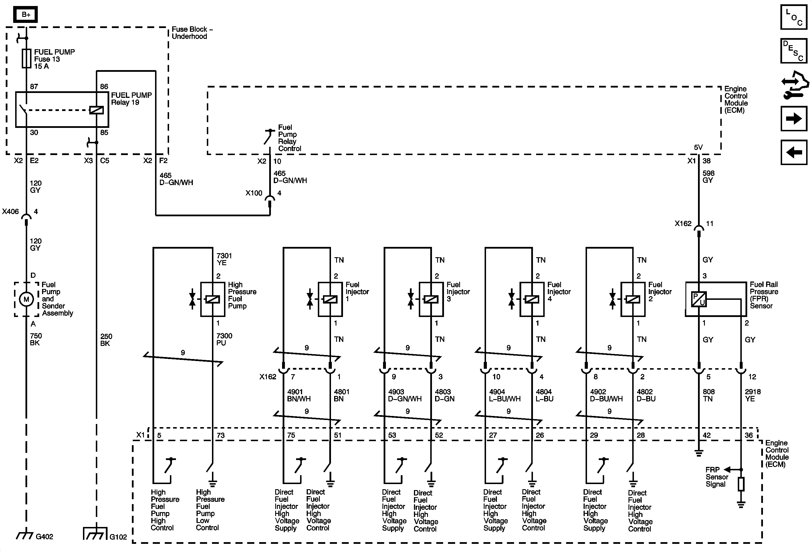
Fuel Controls - Fuel Pump Controls and Fuel Injectors
Engine Data Sensors - Electronic Throttle Controls
Engine Controls Schematic Icons
Figure 7:

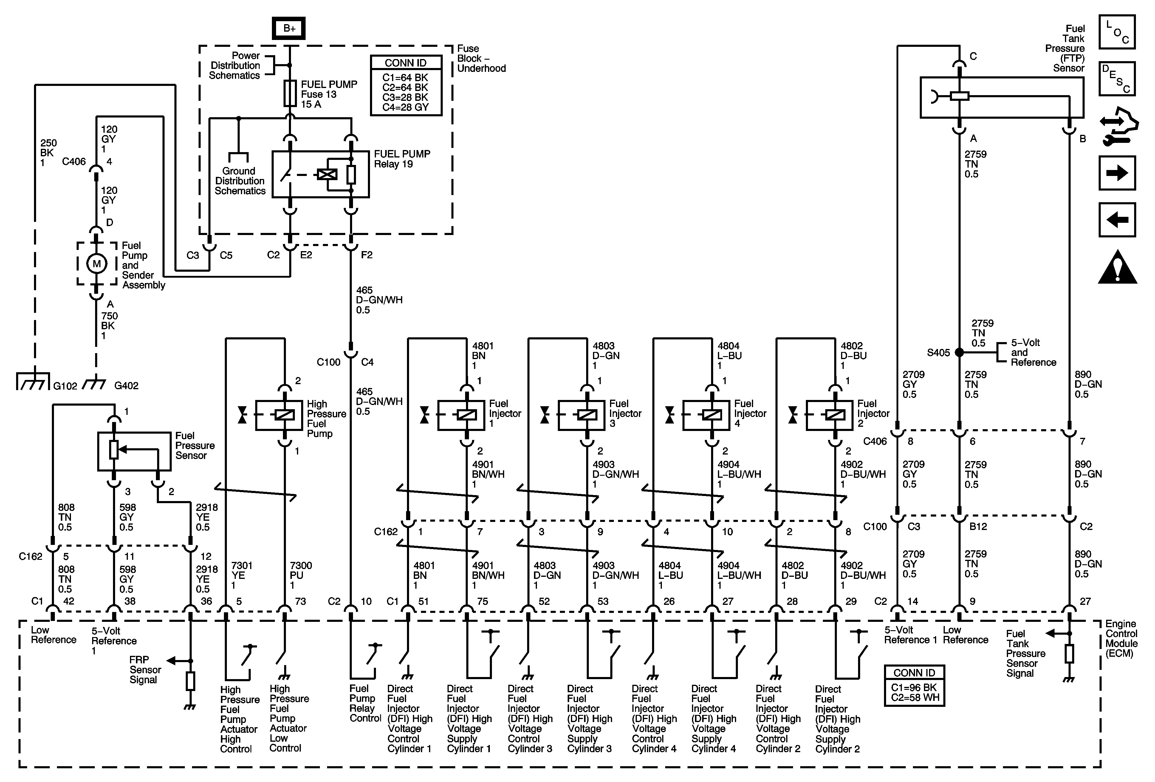
Fuel Controls - Fuel Pump Controls and Fuel Injectors


Object Number: 1829507  Size: FS
Master Electrical Component List
Fuel System Description
Control Module References
Ignition Controls - Ignition System
Ignition Controls - Sensors
Engine Controls Schematic Icons
B+ Bus Bar - 1 of 2
G101 and G102
G101 and G102
G301, G302, G303, G400 and G402
Indicators and Switches
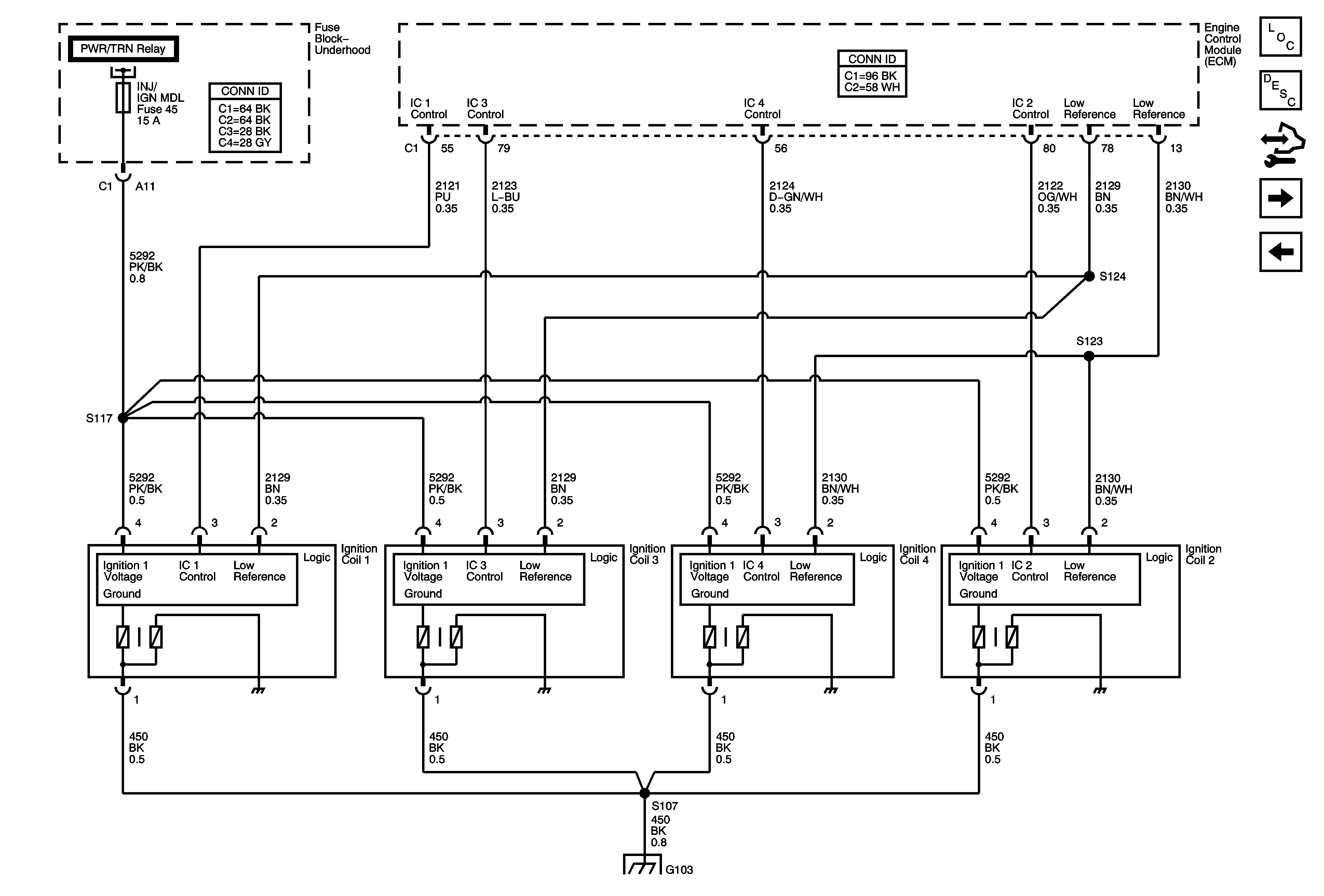
Figure 8:

Ignition Controls - Ignition System


Object Number: 1829510  Size: FS
Master Electrical Component List
Electronic Ignition (EI) System Description
Control Module References
Fuel Controls - EVAP Controls
Fuel Controls - Fuel Pump Controls and Fuel Injectors
G103, G304, G105, G104, and G106
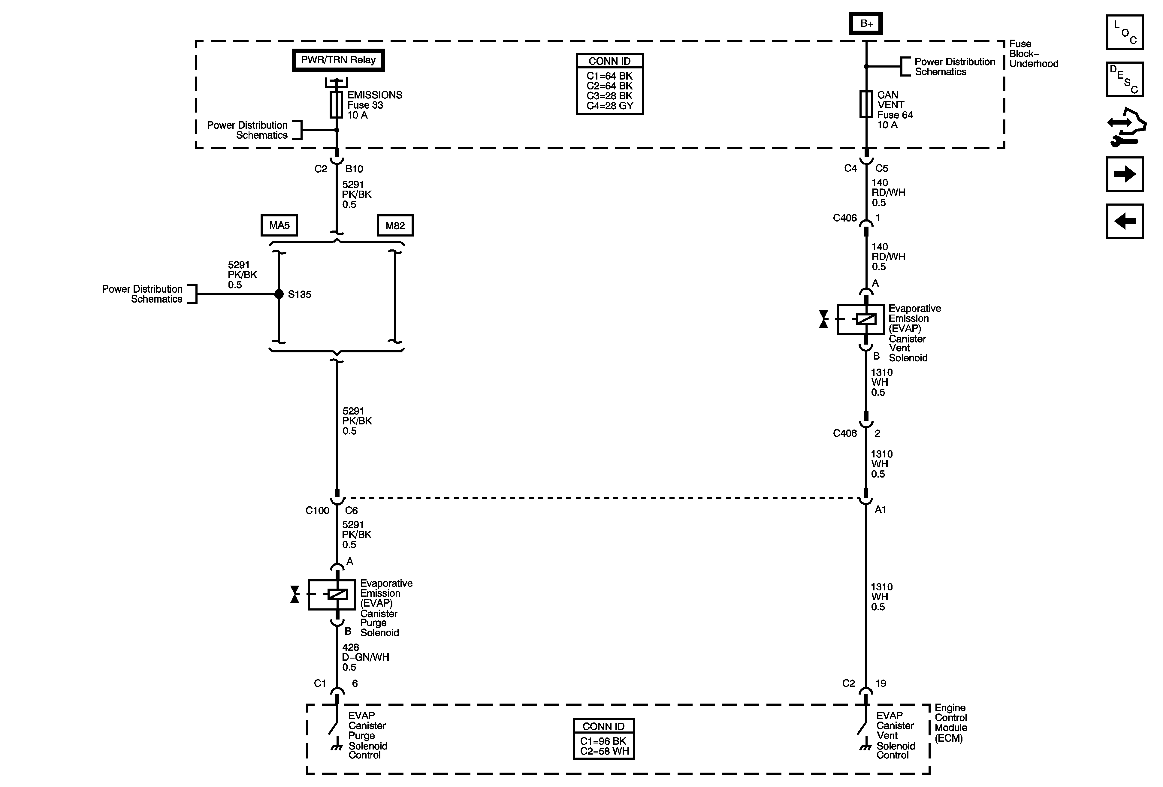
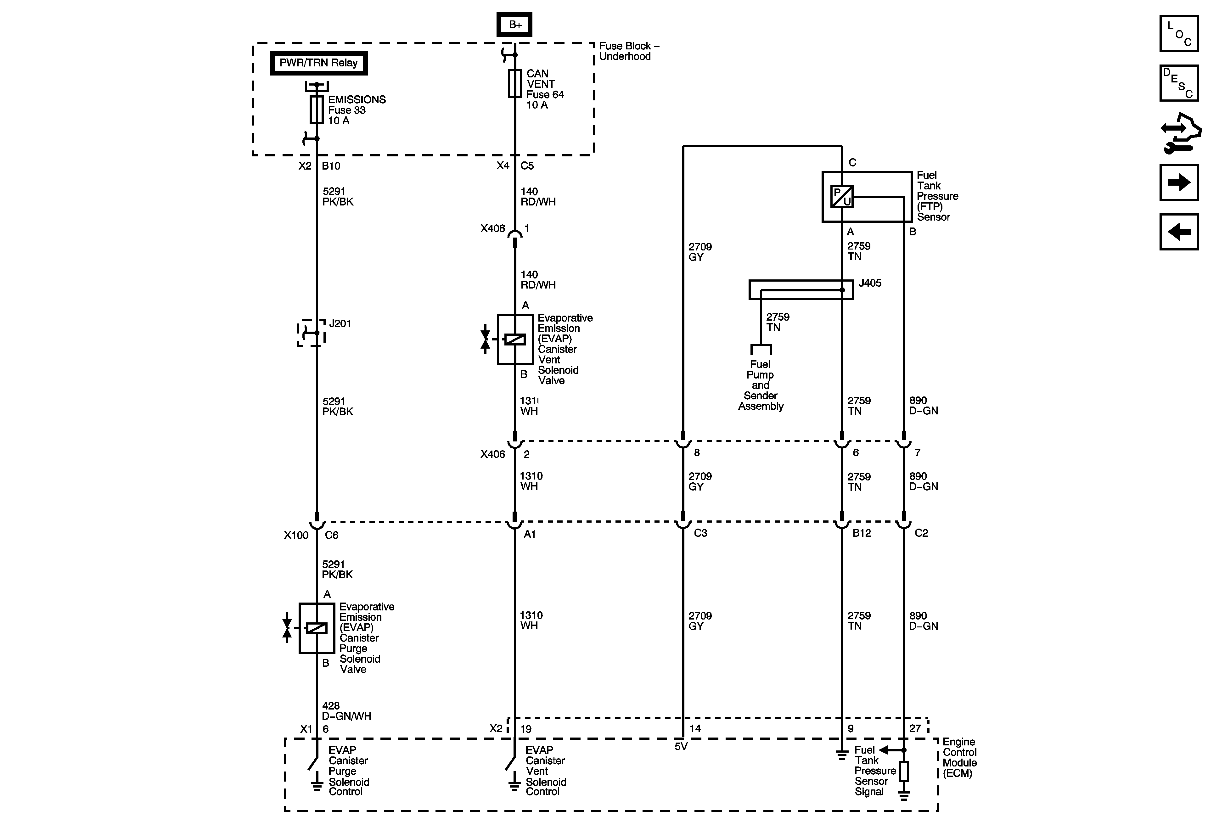
Figure 9:

Fuel Controls - EVAP Controls


Object Number: 1829515  Size: FS
Master Electrical Component List
Fuel System Description
Control Module References
Controlled/Monitored Subsystem References
Ignition Controls - Ignition System
DLC, ECM, EMISSIONS, INJ IGN MDL, and TURBO Fuses, PWR/TRN Relay
ABS, BCK/UP LAMP, CAN VENT, ECM/TRANS, I/P IGN, and OUTLET Fuses, and RUN/CRNK Relay (Underhood Fuse Block), AIRBAG, EPS/STR WHL CNTRL, HVAC/IP IGN, and WPR Fuses (Body Control Module (BCM))
DLC, ECM, EMISSIONS, INJ IGN MDL, and TURBO Fuses, PWR/TRN Relay
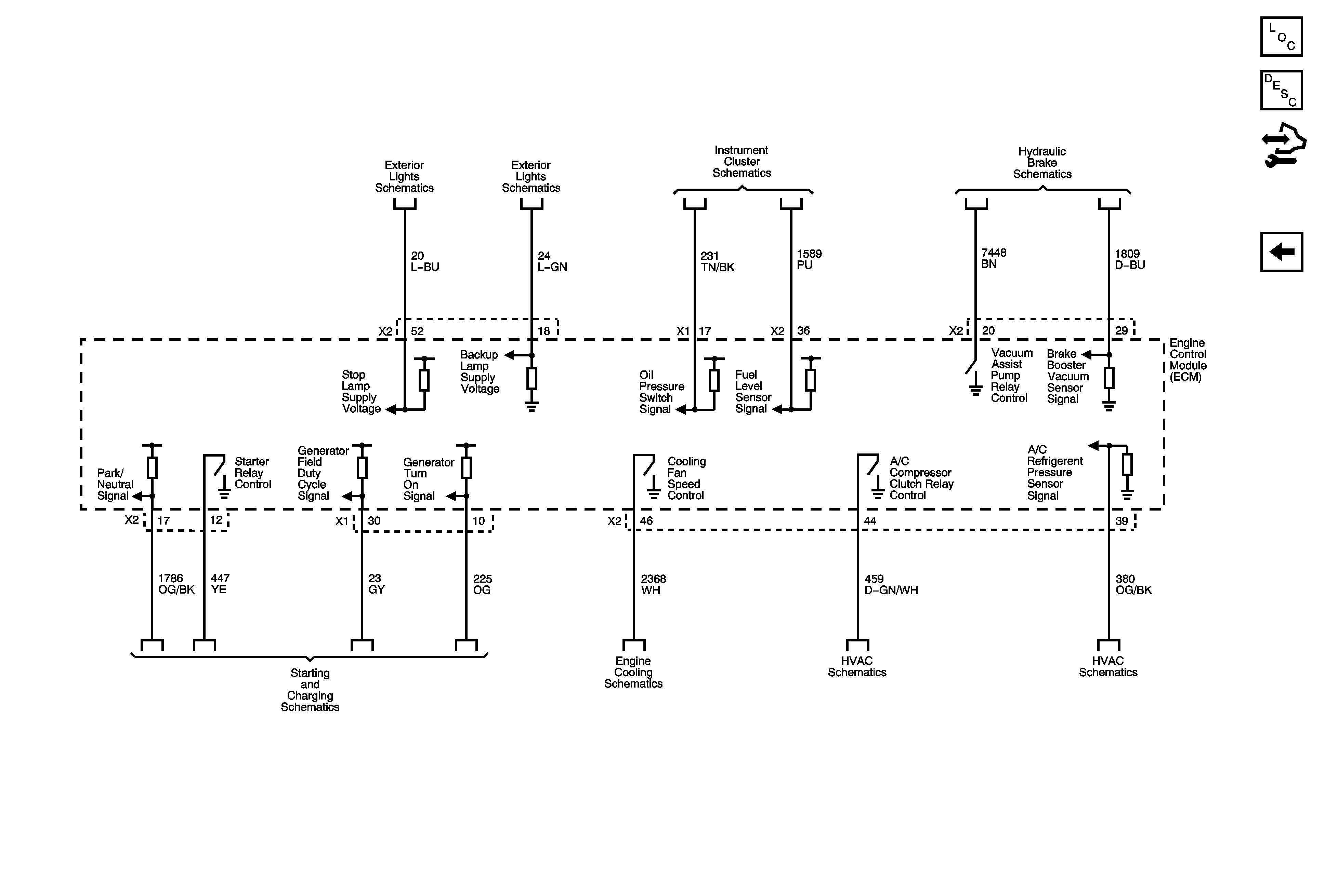
Figure 10:

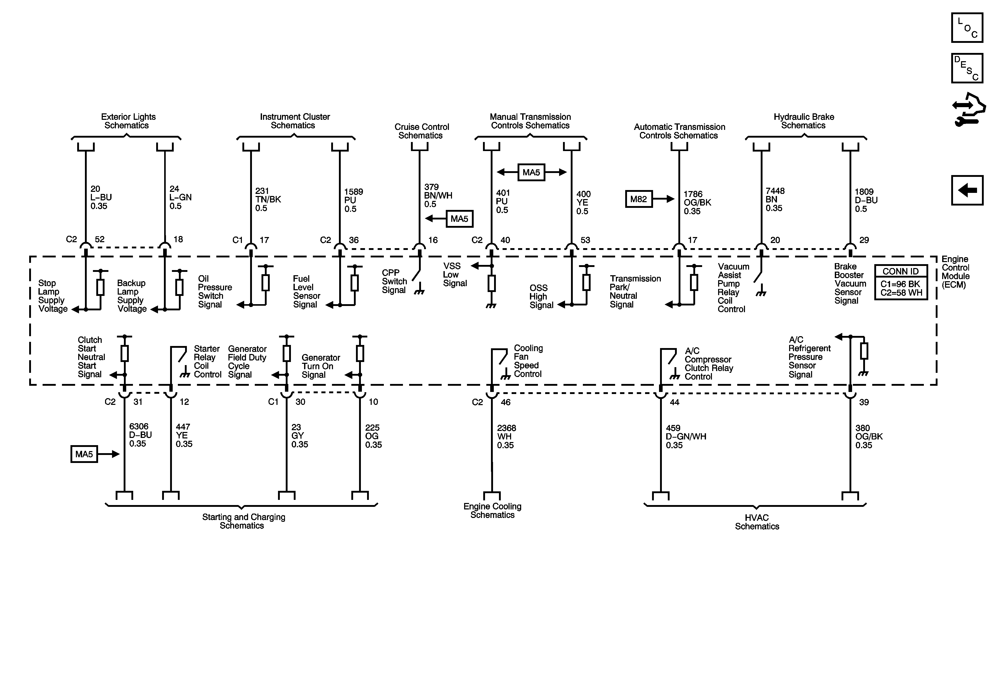
Controlled/Monitored Subsystem References


Object Number: 1829519  Size: FS
Master Electrical Component List
Engine Control Module Description
Control Module References
Fuel Controls - EVAP Controls
Backup Lamps
Indicators and Switches
Cruise Control Schematics
Manual Transmission Schematics
Shift Solenoids, TFT, and VSS
Hydraulic Brakes System Schematics
Starting and Charging Schematics
LNF
Compressor Controls
Figure 1:

Data Link, Ground, MIL, and Power


Object Number: 1871244  Size: FS
Master Electrical Component List
Engine Control Module Description
Control Module References
5-Volt and Low Reference
B+ Bus Bar - 1 of 2
B+ Bus Bar - 1 of 2
TANK VENT, OUTLET, IP IGN, BACKUP, ABS, and ECM TRANS Fuses
B+ Bus Bar - 1 of 2
High Speed LAN
G101 and G102
WINDOWS, DOOR LKS, INT LPS, ECM/TCM, RADIO, and SDM Fuses
G103, G304, G105, G104, and G106
Figure 2:

5-Volt and Low Reference


Object Number: 1871245  Size: FS
Master Electrical Component List
Electronic Ignition (EI) System Description
Control Module References
Engine Data Sensors - Pressure and Temperature
Data Link, Ground, MIL, and Power
Figure 3:

Engine Data Sensors - Pressure and Temperature


Object Number: 1871247  Size: FS
Master Electrical Component List
Air Intake System Description
Control Module References
Engine Data Sensors - Oxygen Sensors
5-Volt and Low Reference
B+ Bus Bar - 1 of 2
EMISSIONS, ECM, and LIGHTER Fuses
G103, G304, G105, G104, and G106
Figure 4:

Engine Data Sensors - Oxygen Sensors


Object Number: 1871249  Size: FS
Master Electrical Component List
Engine Control Module Description
Control Module References
Engine Data Sensors - Engine Throttle Controls
Engine Data Sensors - Pressure and Temperature
B+ Bus Bar - 1 of 2
Figure 5:

Engine Data Sensors - Electronic Throttle Control


Object Number: 1871252  Size: FS
Master Electrical Component List
Throttle Actuator Control (TAC) System Description
Control Module References
Ignition Controls - Sensors
Engine Data Sensors - Oxygen Sensors
Engine Controls Schematic Icons
Figure 6:

Ignition Controls - Sensors


Object Number: 1871253  Size: FS
Master Electrical Component List
Knock Sensor (KS) System Description
Control Module References
Fuel Controls - Fuel Pump Controls and Fuel Injectors
Engine Data Sensors - Engine Throttle Controls
B+ Bus Bar - 1 of 2
Engine Controls Schematic Icons
Figure 7:

Fuel Controls - Fuel Pump Controls and Fuel Injectors


Object Number: 1871255  Size: FS
Master Electrical Component List
Fuel System Description
Control Module References
Ignition Controls - Ignition System
Ignition Controls - Sensors
Engine Controls Schematic Icons
B+ Bus Bar - 1 of 2
G101 and G102
G101 and G102
G301, G102, G303, and G402
Figure 8:

Ignition Controls - Ignition System


Object Number: 1871256  Size: FS
Master Electrical Component List
Electronic Ignition (EI) System Description
Control Module References
Fuel Controls - EVAP Controls
Fuel Controls - Fuel Pump Controls and Fuel Injectors
B+ Bus Bar - 1 of 2
G103, G304, G105, G104, and G106
Figure 9:

Fuel Controls - EVAP Controls


Object Number: 1871257  Size: FS
Master Electrical Component List
Evaporative Emission Control System Description
Control Module References
Controlled/Monitored Subsystem References
Ignition Controls - Ignition System
EMISSIONS, ECM, and LIGHTER Fuses
TANK VENT, OUTLET, IP IGN, BACKUP, ABS, and ECM TRANS Fuses
Figure 10:

Controlled/Monitored Subsystem References


Object Number: 1871259  Size: FS
Master Electrical Component List
Engine Control Module Description
Control Module References
Fuel Controls - EVAP Controls
Stop and Turn Signal Lamps
Backup Lamps
Instrument Cluster
Cruise Control Schematics
Manual Transmission Schematics
Hydraulic Brakes Schematics
Starting and Charging Schematics
Engine Cooling Schematics
Compressor Controls
Compressor Controls