Removal Procedure
Tools Required
| • | J 37772
Front
Wheel Bearing Race Remover |
- Raise the vehicle. Support the vehicle. Refer to
Lifting and Jacking the Vehicle
in General Information.
- Remove the tire and wheel assembly. Refer to
Wheel Removal
in Tires and Wheels.
Important: Suspend the caliper assembly with wire in order to prevent damage to
the brake hose.
- Remove the two caliper carrier bolts.
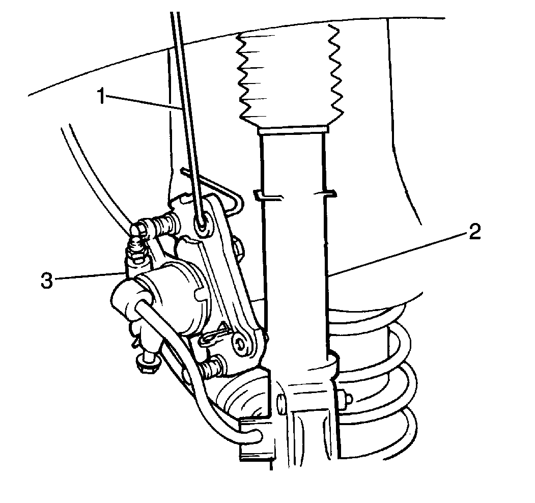
- Remove the brake caliper
(3) from the rotor and the steering knuckle.
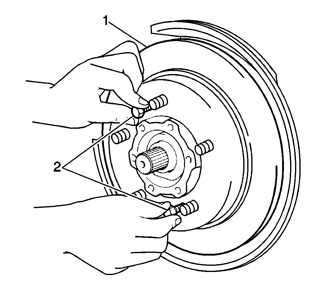
- Remove the brake rotor
(1) from the wheel hub.
If it is not possible to remove the rotor by hand, use the following
steps in order to remove the rotor:
| 5.1. | Install two 8 mm bolts (2) into the rotor. |
| 5.2. | Tighten the bolts (2) in order to force the rotor off of the wheel
hub. |
- On vehicles with two-wheel drive, remove the hub end cap.
- On vehicles with four-wheel drive, remove the free wheel hub.
Refer to
Locking Hub Replacement
in this section.
Notice: Use the correct fastener in the correct location. Replacement fasteners
must be the correct part number for that application. Fasteners requiring
replacement or fasteners requiring the use of thread locking compound or sealant
are identified in the service procedure. Do not use paints, lubricants, or
corrosion inhibitors on fasteners or fastener joint surfaces unless specified.
These coatings affect fastener torque and joint clamping force and may damage
the fastener. Use the correct tightening sequence and specifications when
installing fasteners in order to avoid damage to parts and systems.
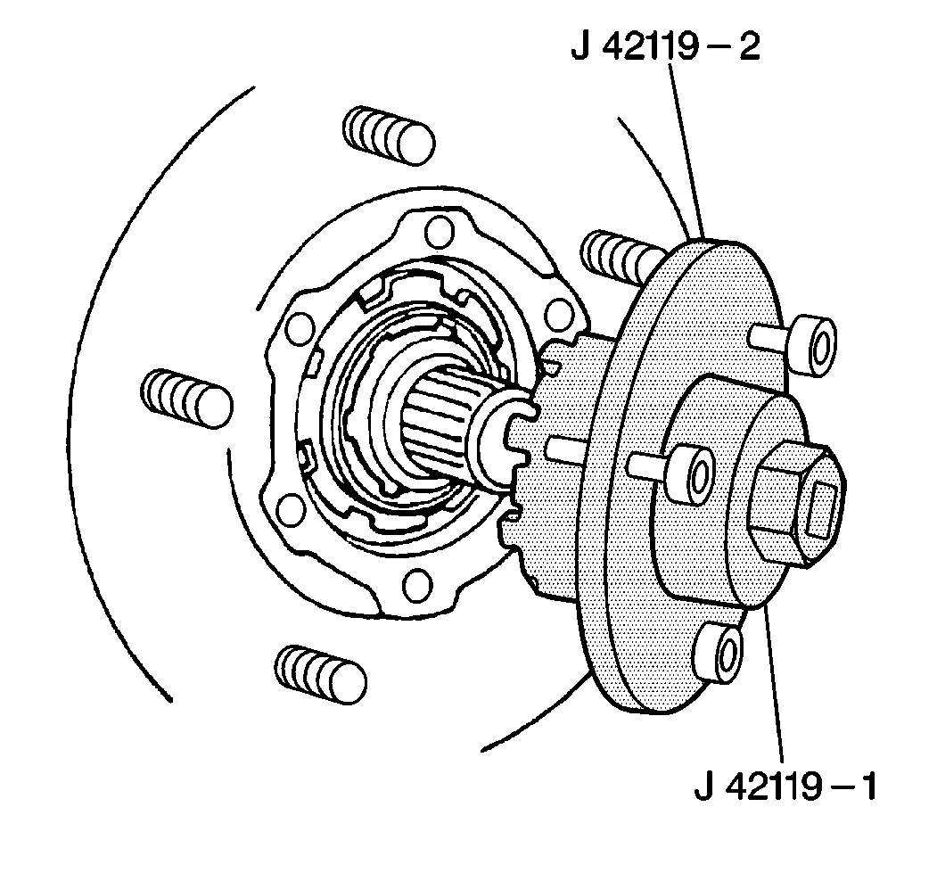
- Use the hub bolts
in order to install the J 42119-1
and the J 42119-2
to
the spindle nut and wheel hub. Be sure to align the wrench with the slots
on the spindle nut.
Tighten
Tighten the hub bolts to 2.5 N·m (12.12 lb in).
- Rotate the spindle nut counterclockwise two full turns in order
to disengage the anti-rotation spring from the spindle nut.
- Remove the J 42119-1
and the J 42119-2
from
the wheel hub.
- Remove the following components from the spindle:
| • | The anti-rotation spring |
| • | The spring back-up plate |
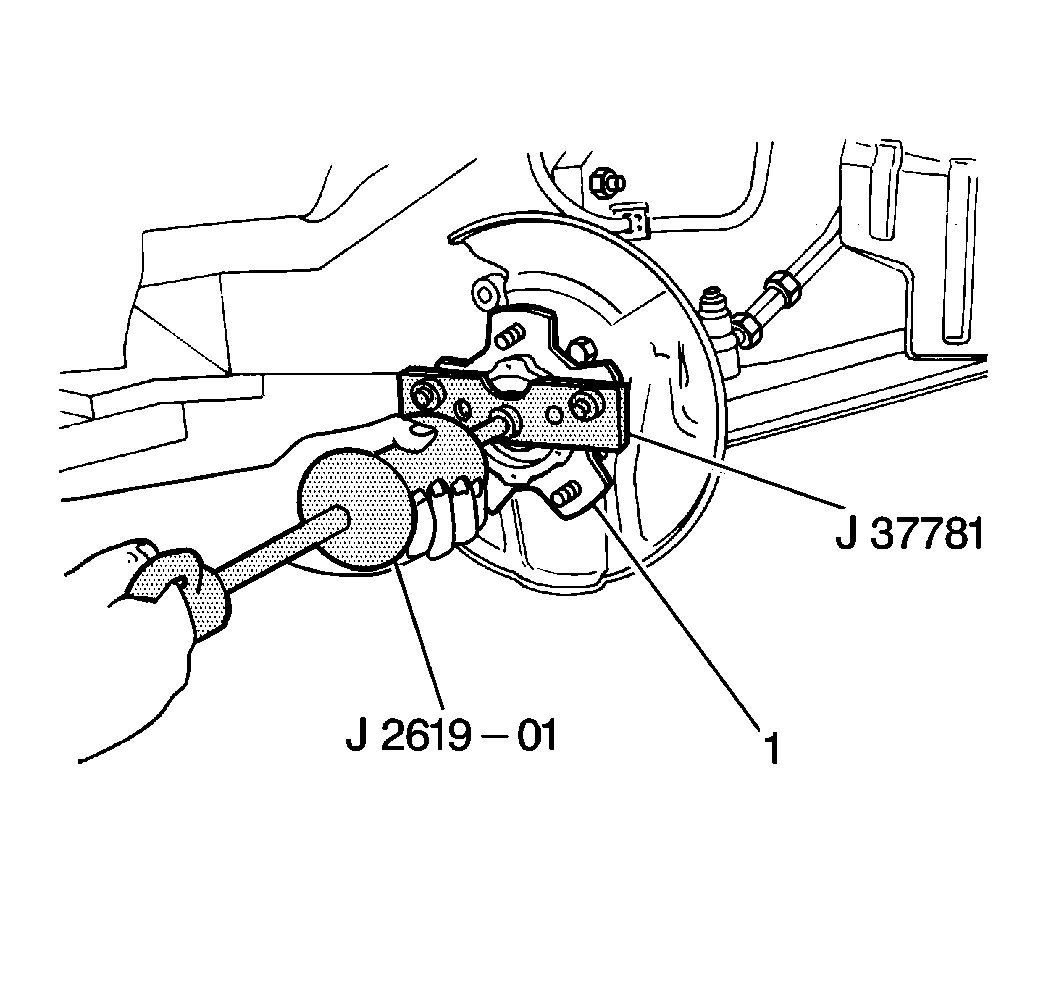
- Use the J 37781
with the J-2619-A
in order to remove the following components from the spindle:
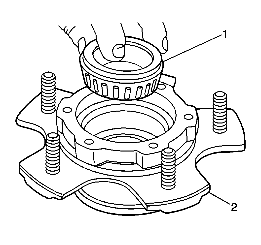
- Remove the outer bearing
(1) from the hub (2).
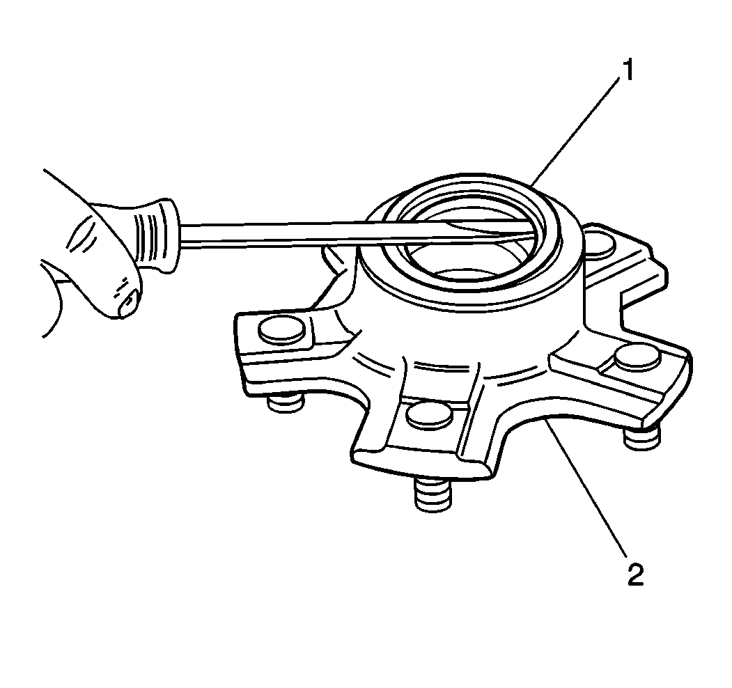
- Remove the wheel bearing
oil seal (1) from the
hub (2).
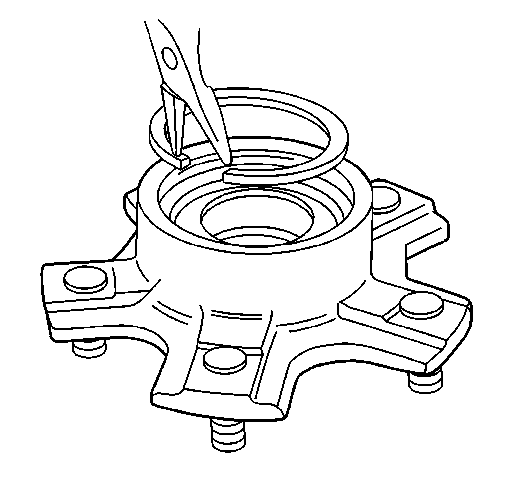
- Remove the snap ring
from the hub.
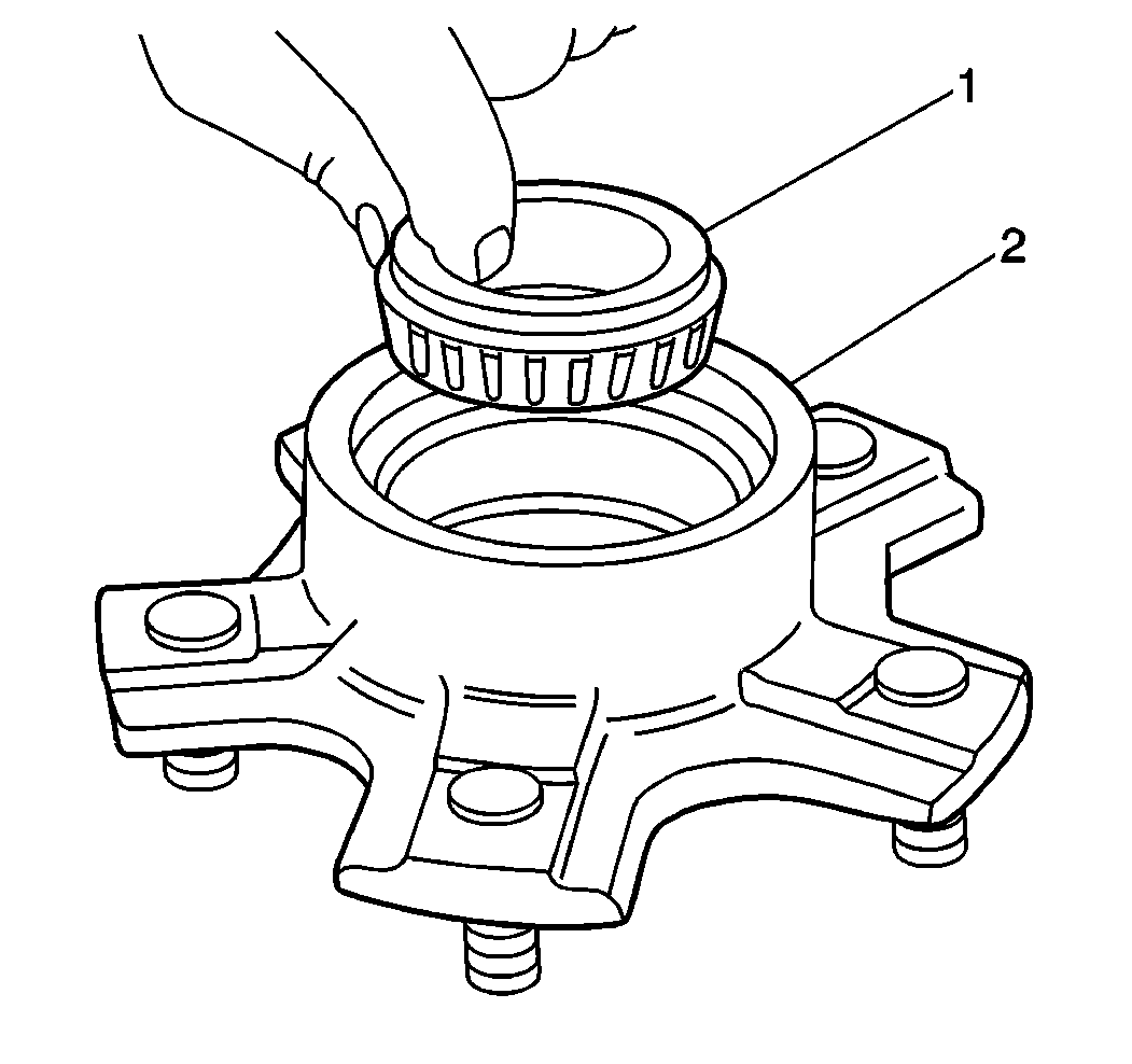
- Remove the inner bearing
(1) from the hub (2).
- If the inner and outer bearing races are scored or pitted, use
the J 37772
and the J 42119-2
in order to remove
the inner and outer bearing races.
- Use a solvent in order to clean any dirt or old grease from the
components.
Installation Procedure
Tools Required
| • | J 37777
Front
Wheel Bearing Race Installer |
| • | J 37774
Wheel
Hub Oil Seal Installer |

- Pack the inner and outer
bearing assemblies with
wheel bearing grease GM P/N 1051344, or the equivalent.
- Use the J 37777
and J 8092
in order
to install the new inner and outer bearing races (if the old races were removed)
to the hub.
- Install the inner bearing (1) to the hub (2).

- Install the snap ring
to the hub.
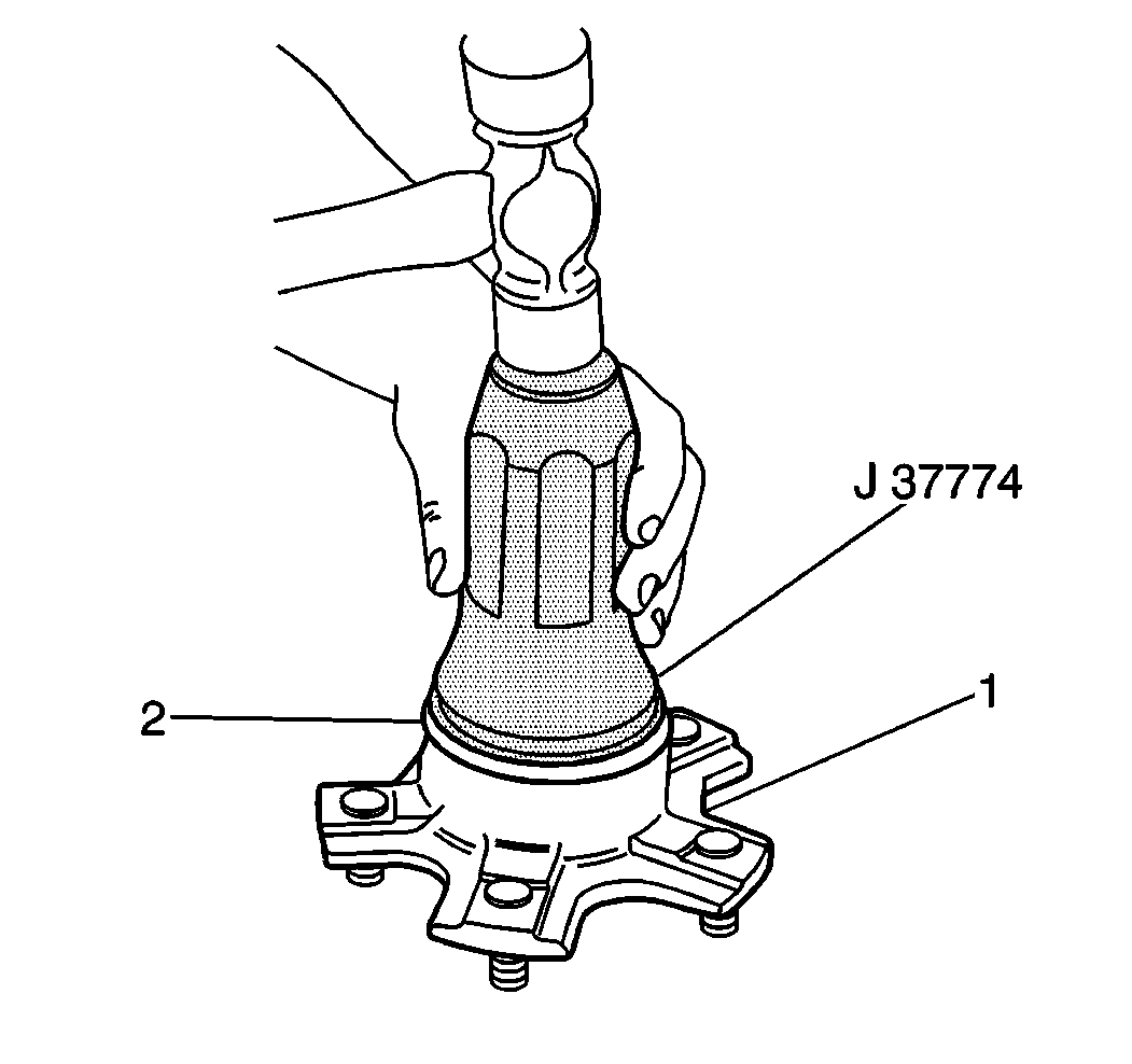
- Use the J 37774
in order to install the wheel bearing
oil seal to the hub.
- Install the outer bearing to the hub.
- Install the wheel hub with the bearings and the oil seals to
the spindle.
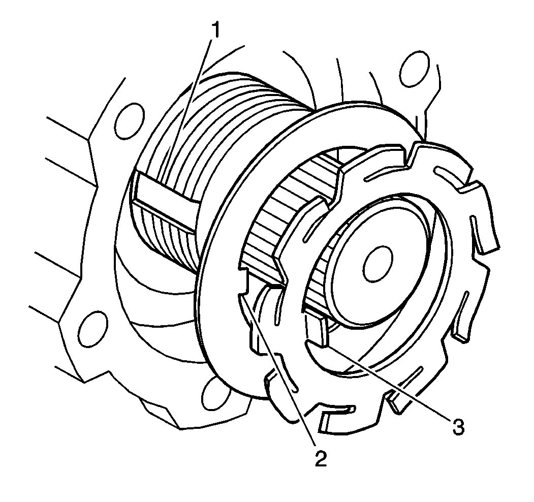
- Install the spring back-up
plate (2).
- Install the anti-rotation spring (3).
- Install the spring nut to the spindle (1).

Notice: Use the correct fastener in the correct location. Replacement fasteners
must be the correct part number for that application. Fasteners requiring
replacement or fasteners requiring the use of thread locking compound or sealant
are identified in the service procedure. Do not use paints, lubricants, or
corrosion inhibitors on fasteners or fastener joint surfaces unless specified.
These coatings affect fastener torque and joint clamping force and may damage
the fastener. Use the correct tightening sequence and specifications when
installing fasteners in order to avoid damage to parts and systems.
- Use the hub bolts
in order to install the J 42119-1
and the J 42119-2
to
the spindle nut and the wheel hub. Be sure to align the wrench with the slots
on the spindle nut.
Tighten
Tighten the spindle nut to 210 N·m (155 lb ft).
- On two-wheel drive models, install the hub end cap.
- On four-wheel drive models, install the free wheel hub. Refer
to
Locking Hub Replacement
in this section.
- Install the brake rotor to the wheel hub.
- Install the brake caliper to the rotor and the knuckle. Secure
the brake caliper with two caliper carrier bolts.
Tighten
Tighten the brake caliper carrier bolts to 88 N·m (65 lb ft).
- Install the tire and wheel assembly. Refer to
Wheel Installation
in Tires and Wheels.
- Lower the vehicle.


