Removal Procedure
Tools Required
| • | J 34757 Circlip Remover |
| • | J 22888-30 Puller Legs |
| • | J 22888-20A Universal Puller |
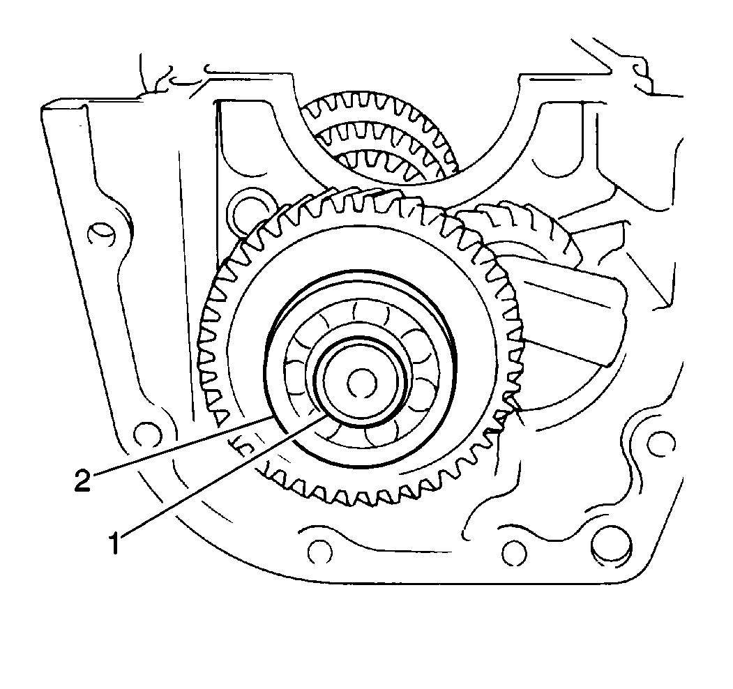
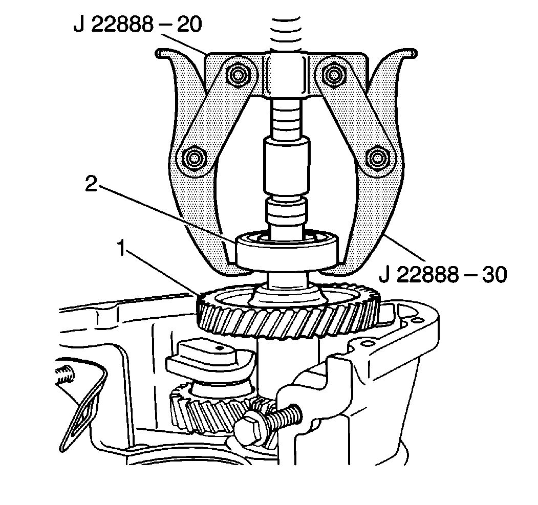
- Use the J 34757 in order to remove the rear countershaft bearing C-clip (1) from the countershaft.
- Use the J 22888-20A with the J 22888-30 in order to remove the rear countershaft bearing (2) from the countershaft.
- Remove the following components from the lower case:
- Remove the following components from the reverse idler shaft:
- Remove the following components from the lower case:
- Remove the front countershaft bearing C-ring (3) from the front countershaft bearing (2).
- Use the following procedure in order to remove the countershaft (1) from the lower case:
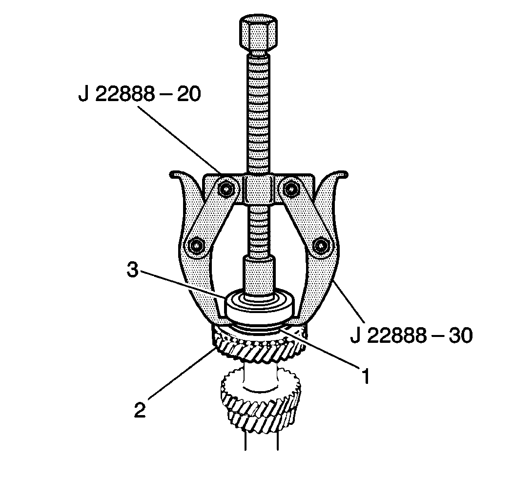
- Use the J 34757 in order to remove the front countershaft bearing C-clip from the countershaft.
- Use the J 22888-20A and the J 22888-30 in order to remove the front countershaft bearing (3) from the countershaft (2).
- Remove the following components from the countershaft:
- Clean the following components with solvent:
- Dry the components thoroughly.
- Inspect all of the gear tooth surfaces for excessive wear or damage.
Remove the following gears by hand:
| 2.1. | The countershaft fifth gear (1) |
| 2.2. | The reverse gear |
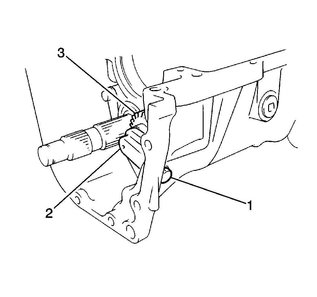
| 3.1. | The reverse idler shaft bolt (1) |
| 3.2. | The reverse idler shaft (2) |
| 3.3. | The reverse idler gear (3) |
| 4.1. | The reverse idler gear thrust washer |
| 4.2. | The reverse idler gear needle bearing |
| 4.3. | The reverse idler gear |
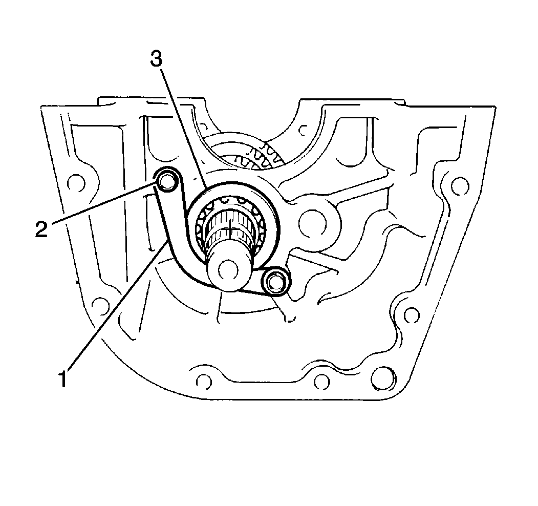
| • | Two bolts (2) |
| • | The countershaft center bearing plate (1) |
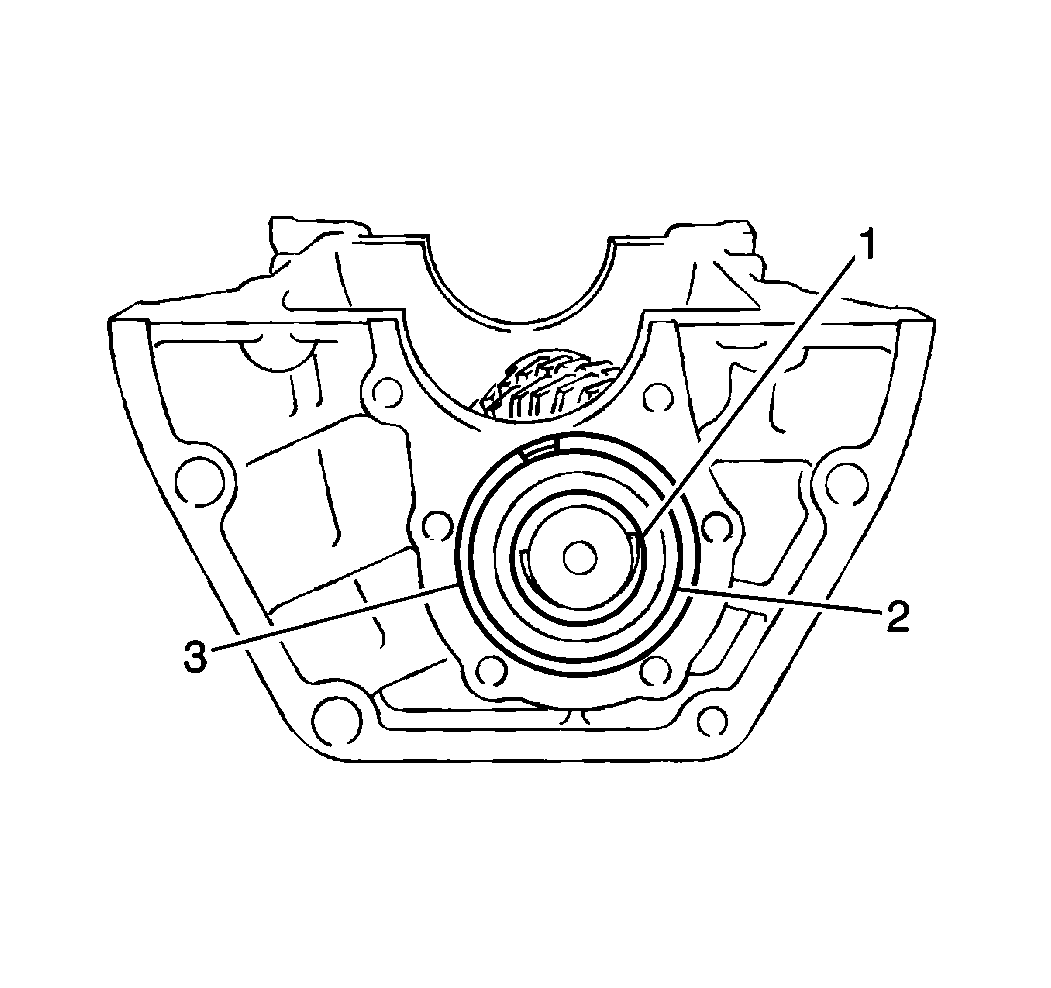
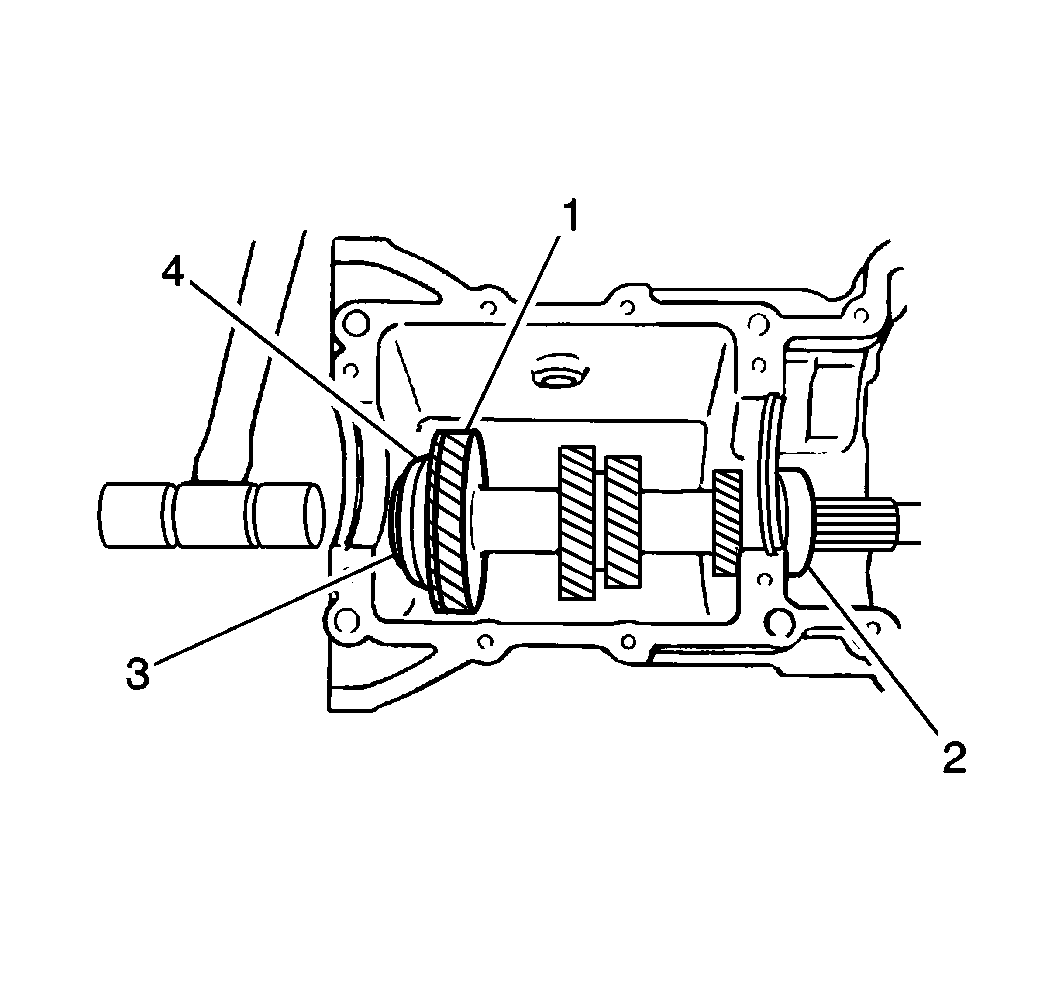
| 7.1. | Lightly tap the countershaft (1) rearward in the lower case. |
| 7.2. | Remove the countershaft center bearing (2) by hand. |
| 7.3. | Pull the countershaft forward. |
| 7.4. | Remove the countershaft from the lower case. |
| 10.1. | The friction gear snap ring |
| 10.2. | The friction gear retainer |
| 10.3. | The friction gear retainer pin |
| 10.4. | The friction gear spring |
| 10.5. | The friction gear |
| • | The lower case mating surfaces |
| • | All of the countershaft components |
Inspect the bearings for smooth rotation. Replace the bearings as necessary.
Installation Procedure
Tools Required
| • | J 37754 Countershaft Bearing Installer |
| • | J 35664 Bearing Installer |
| • | J 35871 Countershaft Front Bearing Installer |
- Install the following components onto the countershaft:
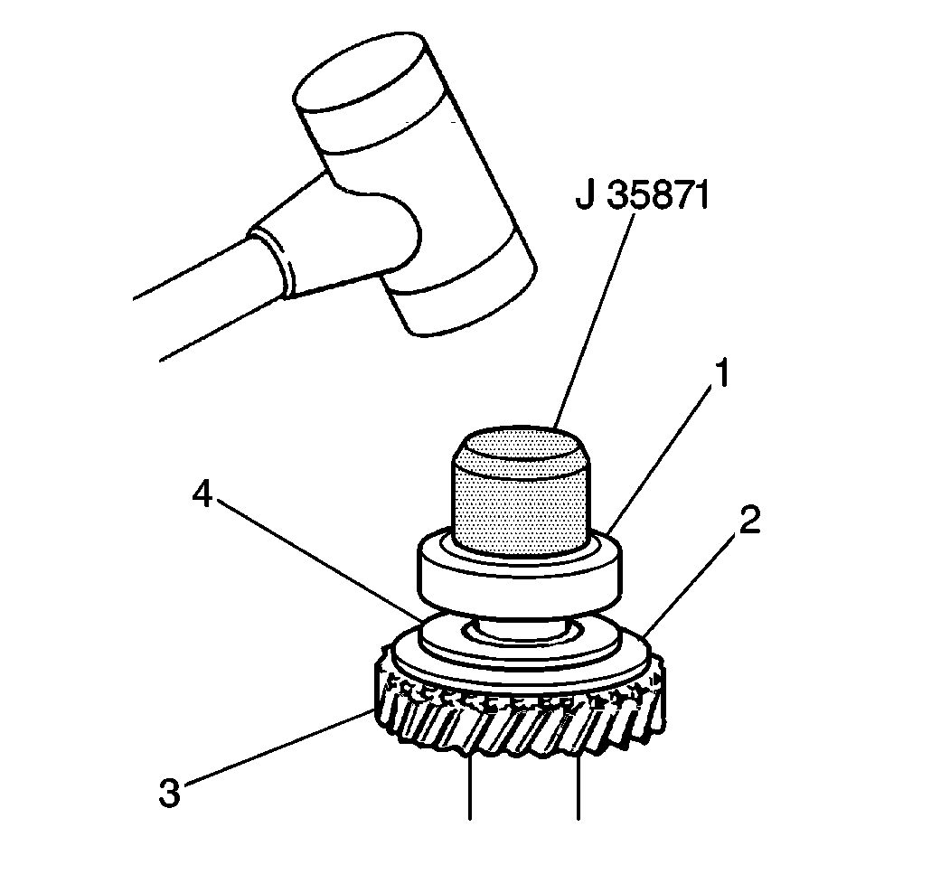
- Use the J 35871 in order to install the front countershaft bearing (1) onto the countershaft (3).
- Install the front countershaft bearing C-clip onto the countershaft.
- Use the following procedure in order to install the following components into the lower case:
- Install the front countershaft bearing C-ring (3) onto the front countershaft bearing (2).
- Apply Loctite™ 414 GM P/N 12345493 or equivalent to the threaded portion of the countershaft center bearing plate bolts.
- Install the countershaft center bearing plate into the lower case.
- Install the following components onto the reverse idler shaft (4):
- Apply Loctite™ 414 GM P/N 12345493 or equivalent to the threaded portion of the reverse idler shaft bolt (3).
- Place the reverse idler gear (2, 7) with the reverse idler shaft (4) into the lower case.
- Secure the reverse idler shaft (4) with one washer and one bolt (3).
- Install the following gears onto the countershaft:
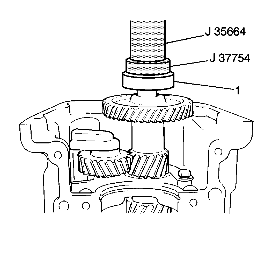
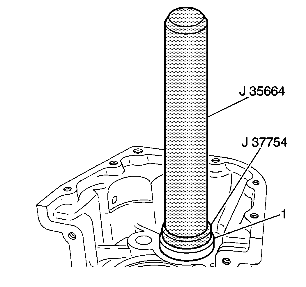
- Use the J 37754 and the J 35664 in order to install the rear countershaft bearing (1) onto the countershaft.
- Install the rear countershaft bearing C-clip onto the countershaft.
| 1.1. | The friction gear |
| 1.2. | The friction gear spring |
| 1.3. | The friction gear retainer pin |
| 1.4. | The friction gear retainer |
| 1.5. | The friction gear snap ring |
| • | The countershaft |
| • | The countershaft center bearing |
| 1. | Place the countershaft center bearing onto the countershaft. |
| 2. | Place the countershaft into the lower case. |
| 3. | Use the J 35664 and the J 37754 in order to press the countershaft and the center bearing (1) into the lower case. |

Position the countershaft so that the front countershaft bearing C-ring (3) makes slight contact with the lower case.
Secure the countershaft center bearing plate with the two bolts.
Tighten
| • | For vehicles with 4-wheel drive, tighten the countershaft center bearing plate bolts to 10 N·m (89 lb in). |
| • | For vehicles with 2-wheel drive, tighten the countershaft center bearing plate bolts to 6 N·m (53 lb in). |
Notice: Use the correct fastener in the correct location. Replacement fasteners must be the correct part number for that application. Fasteners requiring replacement or fasteners requiring the use of thread locking compound or sealant are identified in the service procedure. Do not use paints, lubricants, or corrosion inhibitors on fasteners or fastener joint surfaces unless specified. These coatings affect fastener torque and joint clamping force and may damage the fastener. Use the correct tightening sequence and specifications when installing fasteners in order to avoid damage to parts and systems.
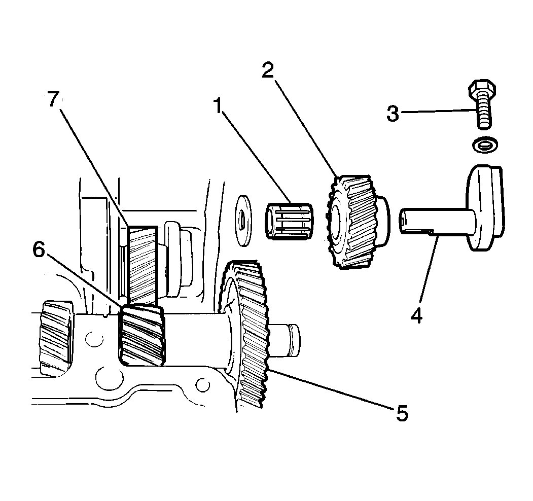
| 8.1. | The reverse idler gear (2, 7) |
| 8.2. | The reverse idler gear needle bearing (1) |
| 8.3. | The reverse idler gear thrust washer |
Important: Use an aluminum washer on the reverse idler shaft bolt (3). Use of an aluminum washer will seat the reverse idler shaft bolt head without causing damage to the lower case.
Tighten
Tighten the reverse idler shaft bolt to 22 N·m (16 lb ft).
| • | The countershaft reverse gear (6) |
| • | The countershaft fifth gear (5) |
