CRUISE CONTROL DISENGAGEMENT ON LT2 (2.0) ENGINES

1987 SUNBIRD MODELS EQUIPPED WITH LT2 ENGINES AND CRUISE CONTROL
These vehicles have an "integrated" cruise system, with the ECM performing the functions of the old cruise module.
Some vehicles with 2.OL-4 OHC (LT2) engines have experienced intermittent disengagement of the cruise control system while traveling at road speeds. When the diagnosis in the Service Manual does not find the problem, the HEI/EST distributor should be visually checked for a possible open or grounded capacitor wire inside the distributor assembly. When the cruise control is being used, the open or intermittent grounding of the capacitor circuit may cause an erroneous signal to be sent to the ECM, resulting in disengagement of the cruise control.
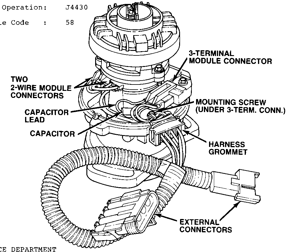
To check the distributor for this condition, remove the cap and inspect the small black wire leading from the red block capacitor to the module connector (see illustration) . If this wire is against the center post in the metal housing, gently pull it away from the housing and check the housing and wire for signs of chafing and arcing. If the wire is burned in two, or if there are signs of arcing that may have resulted from an intermittent ground, replace the 10497847 terminal block assembly (distributor wiring harness with capacitor). If there are no signs of these conditions, leave the capacitor wire positioned away from the center post and reassemble the cap onto the distributor and look elsewhere for the problem.
To replace the terminal block assembly, disconnect the two external connectors from the vehicle wiring harness and the three module connectors from the module terminals. Remove the mounting screw attached to the capacitor base plate using a flexible or jointed nut driver. Lift the terminal block assembly out of the distributor.
Install the new terminal block assembly as follows:
1. Place harness gronmet into slot in edge of housing so that mounting screw enters mounting screw hole in distributor base. Assure that none of the harness wires are routed under or pinched by the capacitor base. Tighten mounting screw.
2. Connect the two 2-wire connectors to module terminals on the side of the distributor away from the harness grommet by first connecting the lead to the inside module terminals, then connecting the pole piece lead to the outer module terminals.
3. Connect the 3-terminal connector to the module terminals closest to the harness grommet, making sure that the small black capacitor lead is positioned away from the center post in the housing to prevent recurrence of the problem.
4. Attach external distributor leads to vehicle wiring harness Assure that all. internal and external connectors are properly seated and latched.
Reassemble the distributor cap and check the vehicle for proper operation.
Warranty Information:
Labor Operation: J4430
Trouble Code : 58

General Motors bulletins are intended for use by professional technicians, not a "do-it-yourselfer". They are written to inform those technicians of conditions that may occur on some vehicles, or to provide information that could assist in the proper service of a vehicle. Properly trained technicians have the equipment, tools, safety instructions and know-how to do a job properly and safely. If a condition is described, do not assume that the bulletin applies to your vehicle, or that your vehicle will have that condition. See a General Motors dealer servicing your brand of General Motors vehicle for information on whether your vehicle may benefit from the information.
