| Table 1: | Fluid Pressure and Circuit Combination |
| Table 2: | Transmission Sensor -- Temperature to Resistance to Voltage (approximate) |
Torque Converter Clutch Solenoid Valve
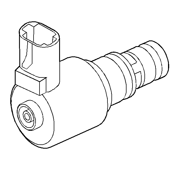
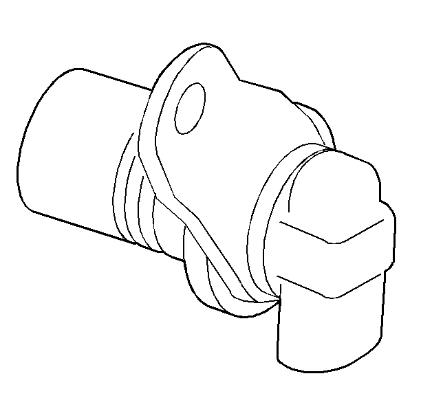
The Torque Converter Clutch Solenoid Valve (TCC Sol. Valve) is a normally closed, pulse width modulated (PWM) solenoid used to control the apply and release of the converter clutch. The PCM operates the solenoid with a negative duty cycle at a fixed frequency of 42 Hz to control the rate of TCC apply/release. The solenoid's ability to ramp the TCC apply and release pressures results in a smoother TCC operation.
When vehicle operating conditions are appropriate to apply the TCC, the PCM immediately increases the duty cycle to approximately 68%. The PCM then ramps the duty cycle up to approximately 93% to achieve full TCC apply pressure. The rate at which the PCM increases the duty cycle controls the TCC apply. Similarly, the PCM also ramps down the TCC solenoid duty cycle to control the TCC release.
Some operating conditions prevent or enable the TCC apply under various conditions. Also if the PCM receives a high voltage signal from the brake switch, indicating that the brake pedal is depressed, the PCM immediately releases the TCC.
Note that the duty cycles in the graph are for example only. Actual duty cycles vary depending on the vehicle application and the vehicle operating conditions.
The TCC Sol. valve resistance should measure between 10.4-10.8 ohms when measured at 20°C (68°F). The resistance would measure approximately 16 ohms at 150°C (300°F).
Automatic Transmission Pressure Control Solenoid Valve
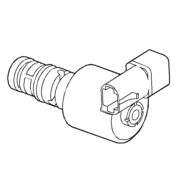
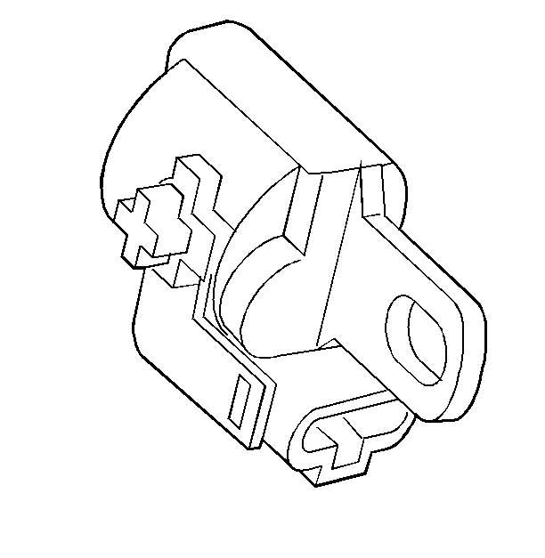
The pressure control (PC) solenoid valve is a precision electronic pressure regulator that controls the transmission line pressure. This control is based on the flow of current through the coil windings of the valve. As the flow of current is increased, the magnetic field which is produced by the coil moves the solenoid's plunger further away from the exhaust port. Opening the exhaust port decreases the output fluid pressure regulated by the PC solenoid valve, which ultimately decreases line pressure.
The PCM controls the PC solenoid valve based on various inputs, including throttle position, fluid temperature, MAP sensor, and gear state.
The PCM controls the PC solenoid valve on a positive duty cycle at a fixed frequency of 614 Hz. Duty cycle is defined as the percent of time current is flowing through the solenoid coil during each cycle. A higher duty cycle provides a greater current flow through the solenoid. The high, positive, side of the PC solenoid valve electrical circuit at the PCM controls the PC solenoid valve operation. The PCM provides a ground path for the circuit, monitors average current and continuously varies the PC solenoid valve duty cycle to maintain the correct average current flowing through the PC solenoid valve.
Duty Cycle | Current | Line Pressure |
|---|---|---|
+5% | 0.02 amps | Maximum |
+40% | 1.1 amps | Minimum |
The resistance on the PC solenoid valve should measure between 3-5 ohms at 20°C (68°F).
Shift Solenoid Valves: 1-2 and 2-3
The shift solenoid valves are two identical, electronic exhaust valves that control upshifts and downshifts in all forward gear ranges. These valves are normally open. These shift solenoid valves work together in a combination of ON and OFF sequences in order to control the positions of the 1-2, 2-3, and 3-4 shift valve trains. The powertrain control module (PCM) monitors numerous inputs to determine the appropriate solenoid state combination and transmission gear for the vehicle operating conditions.
Gear | Solenoid 1-2 | Solenoid 2-3 |
|---|---|---|
PARK, REVERSE, NEUTRAL* | ON | OFF |
FIRST | ON | OFF |
SECOND | OFF | OFF |
THIRD | OFF | ON |
FOURTH | ON | ON |
*Important: The solenoid states are normally ON (1-2) and OFF (2-3) in the P, R, and N gears. However, these may change based on the vehicle speed and the throttle position.
The PCM energizes the shift solenoid valves by providing a ground to the solenoid's electrical circuit. This sends current through the coil winding of the solenoid, thereby creating a magnetic field. The magnetic field repels the plunger inside the solenoid. This seats the solenoid metering ball against the fluid inlet port. This action prevents the exhaust of fluid through the solenoid. It then provides an increase in fluid pressure at the end of the shift valves. This fluid pressure initiates an upshift by moving the shift valves. Refer to the oil flow diagrams in Unit Repair for a complete description of the hydraulic control of the shift valves for each gear range.
The resistance on the shift solenoid valves should measure between 19-24 ohms when measured at 20°C (68°F) and between 24-31 ohms when measured at 88°C (190°F).
The shift solenoid valves should energize when the voltage is greater than 7.5 volts. The shift solenoid valves should de-energize when the voltage is less than one volt.
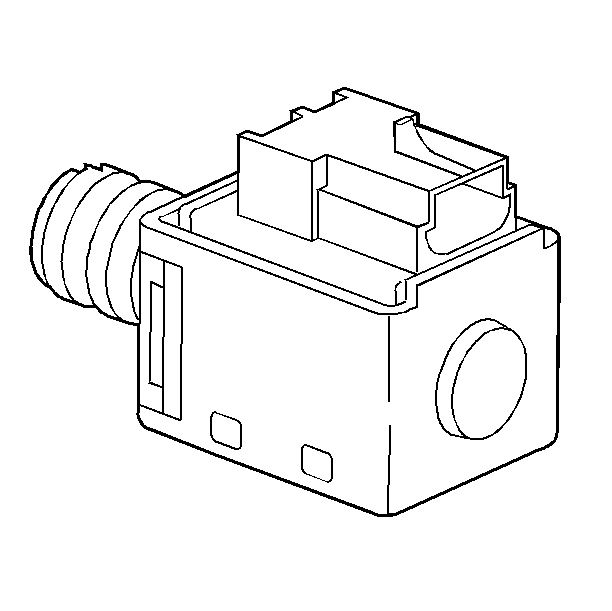
Automatic Transmission Fluid Pressure Manual Valve Position Switch Assembly
The automatic transmission fluid pressure (TFP) manual valve position switch assembly is attached to the control valve body. This assembly contains six fluid pressure switches and the automatic transmission fluid temperature sensor.
Five of the fluid pressure switches are normally-open. These are used to indicate the position of the manual valve. The PCM uses this information to control line pressure, TCC apply and release and shift solenoid operation.
The release pressure switch is used as a diagnostic tool to confirm that the TCC is actually OFF when it has been commanded OFF by the PCM. This switch is normally-closed.
Each fluid pressure switch produces either an open or a ground to the PCM depending on the presence of fluid pressure at the switches. The sequence of open and closed switches produces a combination of voltage readings. The PCM monitors these readings.
The PCM measures TFP manual valve position switch signal voltage from each pin to ground and compares the voltage to a TFP manual valve position switch combination table stored in the PCM memory. If the PCM does not recognize the switch sequence, a diagnostic code will be set as a result. A diagnostic code may also set if the TFP manual valve position switch sequence indicates a gear range selection that conflicts with other sensory inputs to the PCM.
Range Indicator | Fluid Pressure | Circuit | ||||||||||||||
|---|---|---|---|---|---|---|---|---|---|---|---|---|---|---|---|---|
REV | PRND4 | DR | D21 | LO | A | B | C | |||||||||
PARK/NEUTRAL | 0 | 1 | 0 | 0 | 0 | ON | OFF | OFF | ||||||||
REVERSE | 1 | 1 | 0 | 0 | 0 | ON | OFF | ON | ||||||||
OVERDRIVE | 0 | 1 | 1 | 0 | 0 | ON | ON | OFF | ||||||||
Manual THIRD | 0 | 0 | 1 | 0 | 0 | OFF | ON | OFF | ||||||||
Manual SECOND | 0 | 0 | 1 | 1 | 0 | OFF | ON | ON | ||||||||
Manual FIRST | 0 | 0 | 1 | 1 | 1 | ON | ON | ON | ||||||||
| ||||||||||||||||
Valid combinations for Circuits A, B, and C are shown in the table. ON means that the switch is grounded with a resistance less than 50 ohms at 0 volts; OFF means that the switch is open with a resistance greater than 50 K ohms at 12 volts.
Note that resistance should be measured with the engine running. When the transmission's pass through connector is disconnected from the vehicle harness while the engine is running, multiple diagnostic codes will set. Clear these codes when you are finished with this procedure.
Vehicle Speed Sensor
The automatic transmission output (shaft) speed sensor (AT OSS) is a magnetic inductive pickup that relays information relative to vehicle speed to the PCM. Vehicle speed information is used by the PCM to control shift timing, line pressure, and TCC apply and release.
The AT OSS mounts in the case at the speed sensor rotor which is pressed onto the differential. An air gap of 0.27-1.57 mm (0.011-0.062 in) is maintained between the sensor and the teeth on the speed sensor rotor. The sensor consists of a permanent magnet surrounded by a coil of wire. As the differential rotates, an AC signal is induced in the AT OSS. Higher vehicle speeds induce a higher frequency and voltage measurement at the sensor.
Sensor resistance should be 1500-1650 ohms when measured at 20°C (68°F). Output voltage will vary with speed from a minimum of 0.5 volts AC at 25 RPM to 200 volts AC at 1728 RPM.
Automatic Transmission Input Shaft Speed Sensor
The automatic transmission input shaft speed sensor (AT ISS) is a magnetic inductive pickup that relays information about the transmission input speed to the PCM. The PCM uses this information to control the line pressure, TCC apply and release, and the transmission shift patterns. This information is also used to calculate the appropriate operating gear ratios and TCC slippage.
The AT ISS mounts on the transmission case under the channel plate next to the drive sprocket. An air gap of 0.26-2.90 mm (0.010-0.114 in) is maintained between the sensor and the teeth of the drive sprocket. The sensor consists of a permanent magnet surrounded by a coil of wire. As the drive sprocket is driven by the turbine shaft, an AC signal is induced in the AT ISS. Higher engine speeds induce a higher frequency and voltage measurement at the sensor.
Sensor resistance should be 625-725 ohms when measured at 20°C (68°F). Output voltage will vary with speed from a minimum of 0.5 volts AC at 550 RPM, to 200 volts AC at 7000 RPM.
Automatic Transmission Fluid Temperature Sensor
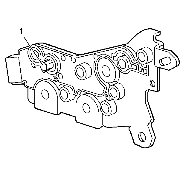
The automatic transmission fluid temperature (TFT) sensor is a negative temperature coefficient thermistor that provides information to the PCM regarding transmission fluid temperature. The TFT sensor (1) is integrated in the automatic transmission fluid pressure (TFP) manual valve position switch assembly which is bolted to the control valve body. The sensor monitors main line pressure from the inside of the control valve body in order to determine the operating temperature of the transmission fluid. The sensor uses an O-ring seal to maintain fluid pressure in the control valve body.
The internal electrical resistance of the sensor varies in relation to the operating temperature of the transmission fluid. The PCM sends a 5-volt reference signal to the sensor. This measures the voltage drop in the electrical circuit. A lower fluid temperature creates a higher resistance in the TFT sensor, thereby measuring a higher voltage signal.
The PCM measures this voltage as another input to help control line pressure, shift schedules and TCC apply. When the TFT reaches 140°C (284°F), the PCM enters hot mode. Above this temperature the PCM modifies the transmission shift schedules and TCC apply in an attempt to reduce fluid temperature by reducing the amount of heat generated by the transmission. During hot mode the PCM applies TCC at all times in Third and Fourth gears. Also, the PCM performs the 2-3 and the 3-4 shifts earlier in order to help reduce the generation of fluid heat.
°C | R low (ohms) | R high (ohms) |
|---|---|---|
0 | 7987 | 10859 |
10 | 4934 | 6407 |
20 | 3106 | 3923 |
30 | 1991 | 2483 |
40 | 1307 | 1611 |
50 | 878 | 1067 |
60 | 605 | 728 |
70 | 425 | 507 |
80 | 304 | 359 |
90 | 221 | 259 |
100 | 163 | 190 |
