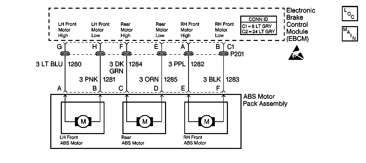
Circuit Description
DTC C1252 diagnoses an ABS motor that energizes longer than expected. The following conditions may cause the longer period of being energized:
| • | A wheel speed sensor malfunctions. |
| • | The left front brake solenoid valve mechanically fails open. |
| • | The ABS brake motor wires are crossed. |
Conditions for Setting the DTC
DTC C1252 can only set during an ABS stop.
A malfunction exists if the EBCM commands the left front ABS channel in release for greater than three seconds.
Action Taken When the DTC Sets
| • | A malfunction DTC stores. |
| • | The ABS disables. |
| • | The ABS warning indicator turns on. |
Conditions for Clearing the DTC
| • | The condition responsible for setting the DTC no longer exists and the Scan Tool Clear DTCs function is used. |
| • | 100 drive cycles pass with no DTC(s) detected. A drive cycle consists of starting the vehicle, driving the vehicle over 16 km/h (10 mph), stopping and then turning the ignition off. |
Diagnostic Aids
The following conditions may cause an intermittent malfunction if the conditions exist in a mechanical part of the system:
| • | Sticking |
| • | Binding |
Use the enhanced diagnostic function of the Scan Tool in order to measure the frequency of the malfunction. DTC C1252 may occur if the vehicle is on ice and the steering wheel is turned to lock during braking. Use the scan tool hydraulic test to ensure the total brake system is functional.
Thoroughly inspect any circuitry that may be causing the intermittent complaint for the following conditions:
| • | Backed out terminals |
| • | Improper mating |
| • | Broken locks |
| • | Improperly formed or damaged terminals |
| • | Poor terminal-to-wiring connections |
| • | Physical damage to the wiring harness |
Clear the DTCs after completing the diagnosis. Test drive the vehicle for three drive cycles in order to verify that the DTC does not reset. Use the following procedure in order to complete one drive cycle:
- Start the vehicle.
- Drive the vehicle over 16 km/h (10 mph).
- Stop the vehicle.
- Turn the ignition to the OFF position.
Step | Action | Value(s) | Yes | No | ||||
|---|---|---|---|---|---|---|---|---|
|
Important: Zero the J 39200 test leads before making any resistance measurements. Refer to the J 39200 user's manual. Important: Inspect for and correct the following conditions in the base brake or
suspension system before proceeding with the DTC diagnosis:
| ||||||||
1 | Was the Diagnostic System Check performed? | -- | Go to Diagnostic System Check | |||||
2 |
Do not start the engine. Are there any wheel speed sensor DTCs that set as current DTCs? | -- | Go to the appropriate DTC table. | |||||
3 |
Do any of the wheel speed sensors indicate erratic or intermittent operation? | -- | Go to the Excessive Wheel Speed Sensor Variation DTC for the affected wheel | |||||
4 |
Do not start the engine. Did the brake pedal fall? | -- | ||||||
5 |
Does the brake pedal fall? | -- | ||||||
6 |
Did the brake pedal fall? | -- | ||||||
7 |
Does the brake pedal fall? | -- | ||||||
8 | Did the brake pedal rise? | -- | ||||||
9 |
(The ABS brake modulator left front gear is the large gear that is the closest to the front when the ABS brake modulator is mounted in the vehicle.) Is it possible to rotate the ABS brake modulator left front gear by hand? | -- | ||||||
10 | Replace the ABS brake modulator. Refer to Brake Modulator/Master Cylinder Assembly Replacement . Is the repair complete? | -- | Go to Diagnostic System Check | -- | ||||
11 | Replace the ABS brake solenoid valve that was originally in the left front ABS brake solenoid valve position. Refer to Brake Solenoid Valve Replacement . Is the repair complete? | -- | Go to Diagnostic System Check | -- | ||||
12 | Repair the crossed wires to the left front ABS motor (CKT 1280 and CKT 1281). Is the repair complete? | -- | Go to Diagnostic System Check | -- | ||||
13 | Replace the ABS brake motor pack. Refer to ABS Motor Pack Replacement . Is the repair complete? | -- | Go to Diagnostic System Check | -- | ||||
14 | The malfunction is intermittent or is not present at this time. Refer to Diagnostic Aids for more information. Is the action complete? | -- | System OK | -- | ||||
