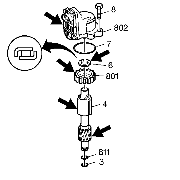
- Clean the governor assembly (4) in solvent.
- Inspect the governor for the following:
- Inspect the governor drive gear for the following:
- Inspect the speed sensor rotor (801) for nicks, burrs, or damaged teeth.
- Hold the governor upside down and pour solvent or Dexron III® into the governor shaft.
- Inspect for leaks around the ball valves.
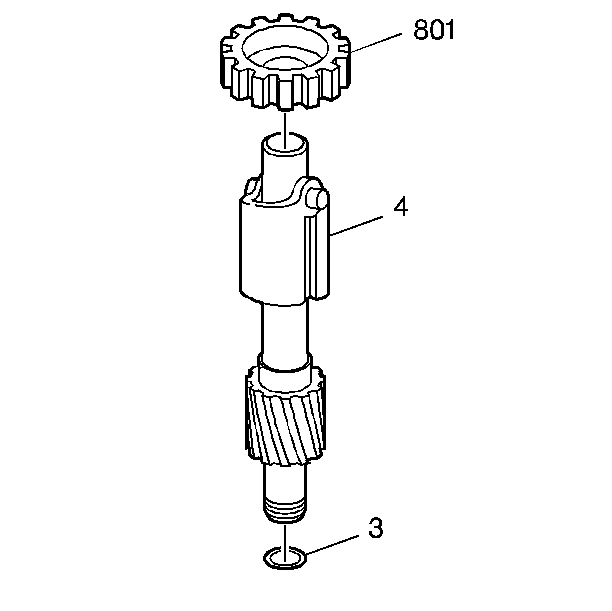
- Affix a new fluid seal (3) onto the governor.
- Insert the speed sensor rotor (801) onto the governor.
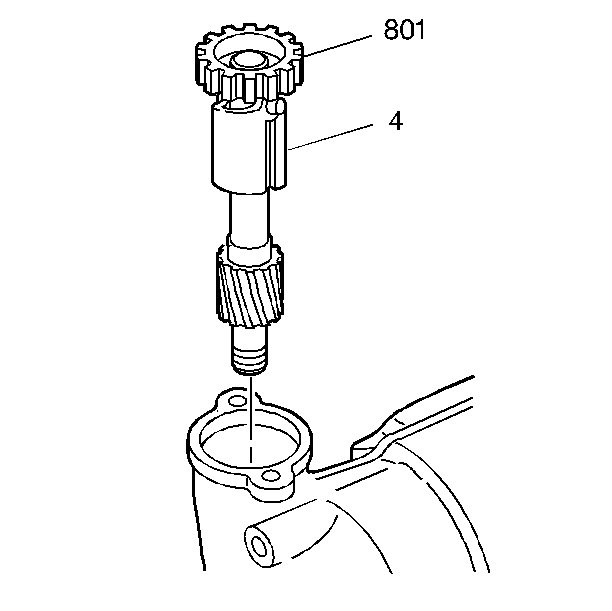
- Install the governor assembly (4) into the case.
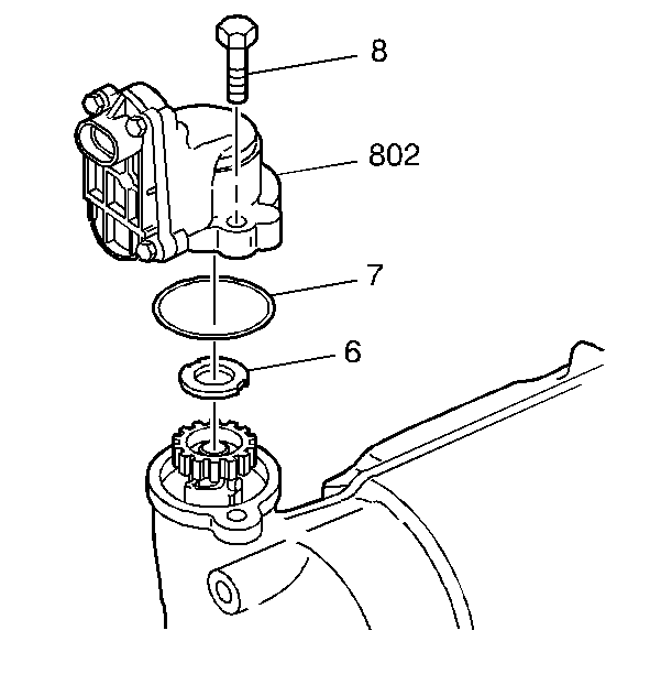
- Install the governor thrust bearing assembly (6) onto the rotor.
- Install a new governor cover seal (7) onto the case.
- Position the governor cover (802) onto the case and finger start two bolts (8).
| • | A blocked oil passage |
| • | Damaged springs |
| • | Missing ball valves |
| • | Binding weights |
| • | Damaged teeth |
| • | Teeth wear |
| • | Burrs |
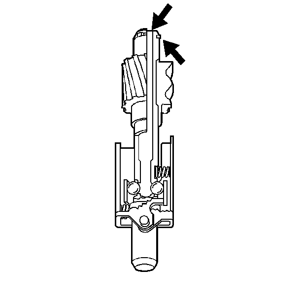
Important: During the leak inspection, allow the governor weights to hold the ball valves freely in their seats.
Notice: Use the correct fastener in the correct location. Replacement fasteners must be the correct part number for that application. Fasteners requiring replacement or fasteners requiring the use of thread locking compound or sealant are identified in the service procedure. Do not use paints, lubricants, or corrosion inhibitors on fasteners or fastener joint surfaces unless specified. These coatings affect fastener torque and joint clamping force and may damage the fastener. Use the correct tightening sequence and specifications when installing fasteners in order to avoid damage to parts and systems.
Tighten
Tighten the bolts to 11 N·m (98 lb in).
