Electronic Leak Detection Method
Tools Required
J 39400 Halogen Leak Detector
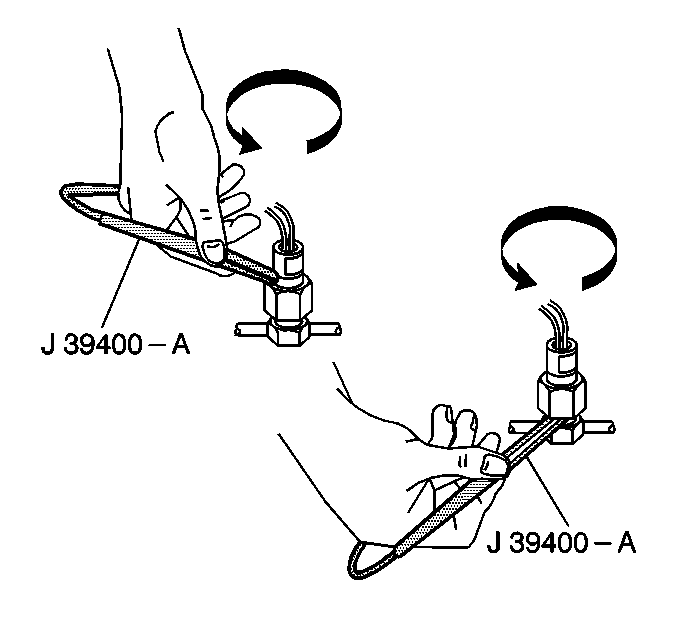
Use the J 39400 when testing for refrigeration system leaks. This unit operates on a 12 volt DC and provides an audible signal which increases in frequency when a refrigerant leak is detected. Properly calibrate the tool to the instructions and use at the proper setting for the system being tested. The J 39400 has the following three settings:
| • | R-12 |
| • | R-134a |
| • | Gross leaks -- for isolating very large leaks already found at one of the other settings |
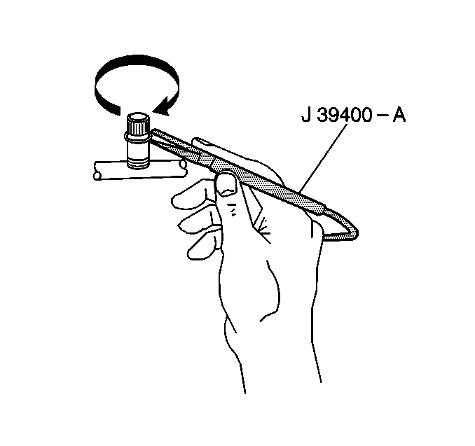
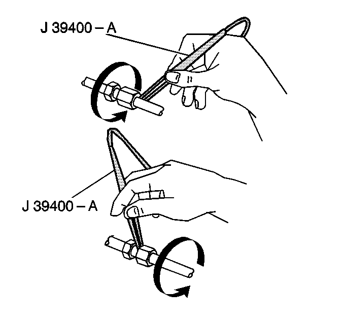
The J 39400 is sensitive to windshield washing solution, many solvents and cleaners, and some adhesives. Work on a clean and dry surface. The following connections may all be tested using this detector, each connection being completely circled moving at 20-50 mm (1-2 inches) per second with the tip of the probe no more than 6 mm (0.25 in) from the surface:
- Test the refrigerant pressure sensor.
- Test the service valves.
- Test the entire length of the hoses or tubes.
- Test the evaporator core hose or tube connections.
- Test the compressor rear head.
- Test the compressor hose assembly connections.
- Test the accumulator connections.
- A leak is indicated when the audible tone goes from a steady 1-2 clicks per second to a solid alarm. The balance knob should be adjusted frequently in order to maintain the 1-2 clicks per second.


If a leak is not found, proceed to the Refrigerant Leak Diagnosis table.
Step | Action | Yes | No | ||||
|---|---|---|---|---|---|---|---|
DEFINITION: Inspecting the refrigeration system for leaks using the J 39400 . | |||||||
1 |
Did you find and repair the condition? | System OK | |||||
2 |
Did you find and repair the condition? | System OK | |||||
3 | Test the condenser for leaks at the following areas:
Did you find a leak? | ||||||
4 | Replace the condenser. Refer to Condenser Replacement . Did you complete the repair? | - | |||||
5 | Test the compressor seal for leaks using the following procedure:
Does the leak detector indicate a leak? | ||||||
6 | Replace the compressor seal. Refer to Compressor Shaft Seal Removal (V5 - Direct Mount) or Compressor Shaft Seal Removal (V5 - Conventional Mount) and Compressor Shaft Seal Install (V5 - Direct Mount) or Compressor Shaft Seal Install (V5 - Conventional Mount) . Did you complete the repair? | -- | |||||
7 | Test the evaporator for leaks using the following procedure:
Does the leak detector indicate a leak | ||||||
8 | Replace the evaporator core. Refer to Air Conditioning Evaporator Core Replacement . Did you complete the repair? | -- | |||||
9 | Test for proper system performance. Refer to Cooling Insufficient - Air Conditioning (A/C) System . Does the system operate correctly and no further system leaks are indicated? | System OK | Go to Florescent Leak Detection Method | ||||
Florescent Leak Detection Method
Tools Required
| • | J 41447 R-134a Tracer Dye |
| • | J 41436-1 R-134a Tracer Dye Injector |
| • | J 28428-E High Intensity Black Light |
Notice: The tracer dye J 41447 was developed for use with the A/C Refrigerant 134a (R-134a) equipped vehicles or with vehicles that have been retrofitted from R-12 to R-134a. Do not use any other tracer dye in the R-134a system. Use of another dye may affect the system reliability and cause premature compressor failure. Use only a 1/4 oz. charge of the dye. Larger amounts may compromise the reliability of the A/C system. After adding the tracer dye, clean the service valves and all affected surfaces of the dye with GM Engine Degreaser GM P/N 1050436 or an equivalent in order to prevent a false diagnosis.
The R-134a refrigerant is uniquely different from the R-12 used in the past and may require additional methods for leak detection. The R-134a molecule is smaller than the R-12 molecule and can leak through smaller openings. R-134a also does not contain chlorine which was easily detected using the black light. The efflorescence leak detection method is meant to be used in conjunction with the electronic method, and will pinpoint smaller leaks. The R-134a takes time to work. Depending on the rate of the leak, the dye may take up to 7 days to become visible.
Liquid Leak Detection/Pressure Testing Methods
Due to their lack of sensitivity and restricted visibility in today's refrigerant systems, liquid/bubble leak detectors have very limited usefulness. Therefore, the liquid leak detection/pressure testing methods are not recommended for this vehicle.
Service Port Seal/Cap
The primary seal for the service ports is the sealing cap. The cap contains a specially designed O-ring or gasket which provides a leak free seal. Should the cap be loose, missing, or the wrong usage, a loss of refrigerant could result.
