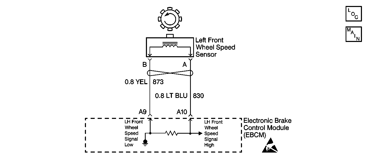
Circuit Description
As a toothed ring passes by the wheel speed sensor, changes in the electromagnetic field cause the wheel speed sensor to produce an AC voltage signal. The EBCM uses the frequency of the AC signal to calculate the wheel speed.
Conditions for Running the DTC
| • | No wheel speed sensor circuit hardware malfunctions are present. |
| • | The brake switch is OFF. |
Conditions for Setting the DTC
The EBCM detects a rapid variation in the wheel speed. The wheel speed changes by 16 km/h (10 mph) or more in 0.01 seconds. The change must occur 3 times with no more than 1 second between occurrences.
Action Taken When the DTC Sets
| • | The EBCM stores a malfunction DTC. |
| • | The EBCM disables the ABS and ETS. |
| • | The ABS warning indicator turns ON. |
| • | The TRAC OFF indicator turns ON. |
Conditions for Clearing the DTC
| • | The condition responsible for setting the DTC no longer exists and the Scan Tool Clear DTCs function is used. |
| • | 100 drive cycles pass with no DTCs detected. A drive cycle consists of starting the vehicle, driving the vehicle over 16 km/h (10 mph), stopping and then turning the ignition OFF. |
Diagnostic Aids
Thoroughly inspect the wiring and the connectors. An incomplete inspection of the wiring and the connectors may result in a misdiagnosis, causing a part replacement with the reappearance of the malfunction.
The following are possible causes of the malfunction:
| • | Poor connections |
| • | Broken wire insulation |
| • | A break in the wire inside the insulation |
| • | Loose or damaged toothed ring |
| • | Improper wheel speed sensor air gap. |
| • | Loose or damaged hub/bearing assembly |
| • | Loose or damaged wheel speed sensor |
| • | Loose or damaged CV joint |
| • | Brake lamp switch malfunction. |
If an intermittent malfunction exists, refer to Testing for Intermittent Conditions and Poor Connections in Wiring Systems.
Test Description
The numbers below refer to the step numbers on the diagnostic table.
-
This step tests the wheel speed sensor for the proper resistance value.
-
This step ensures that the wheel speed sensor generates the proper voltage.
-
This step tests whether the wheel speed sensor circuits are shorted together.
Step | Action | Value(s) | Yes | No | ||||||
|---|---|---|---|---|---|---|---|---|---|---|
1 | Did you perform the ABS Diagnostic System Check? | -- | Go to Step 2 | |||||||
2 |
Does the scan tool indicate the suspect wheel speed varies from the speeds of the other wheels? | -- | Go to Step 3 | Go to Testing for Intermittent Conditions and Poor Connections in Wiring Systems | ||||||
3 | Inspect the following components for physical damage:
Did you find and correct the condition? | -- | Go to Step 11 | Go to Step 4 | ||||||
Does the resistance measure within the specified range? | 1530-1870 ohms | Go to Step 5 | Go to Step 9 | |||||||
Does the AC voltage measure greater than the specified value? | 100 mV | Go to Step 6 | Go to Step 9 | |||||||
6 | Inspect for poor connections/terminal tension at the wheel speed sensor harness connector. Refer to Testing for Intermittent Conditions and Poor Connections and Connector Repairs in Wiring Systems. Did you find and correct the condition? | -- | Go to Step 11 | Go to Step 7 | ||||||
Did you find and correct the condition? | -- | Go to Step 11 | Go to Step 8 | |||||||
8 | Inspect for poor connections/terminal tension at the EBCM harness connector. Refer to Testing for Intermittent Conditions and Poor Connections and Connector Repairs in Wiring Systems. Did you find and correct the condition? | -- | Go to Step 11 | Go to Step 10 | ||||||
9 | Replace the wheel speed sensor. Refer to Front Wheel Speed Sensor Replacement . Did you complete the replacement? | -- | Go to Step 11 | -- | ||||||
10 | Replace the EBCM. Refer to Electronic Brake Control Module Replacement . Did you complete the replacement? | -- | Go to Step 11 | -- | ||||||
11 |
Does the DTC reset? | -- | Go to Step 2 | System OK |
