Crankshaft Cleaning and Inspection
Tools Required
| • | J 7872 Magnetic Base Dial Indicator Set |
| • | J 8001 Dial Indicator Set |
| • | J 26900-13 Magnetic indicator Base |
Important: Use care when handling the crankshaft. Avoid damage to the bearing surfaces.
- Clean the oil, sludge, and carbon from the crankshaft with solvent.
- Thoroughly clean all oil passages and inspect for restrictions and burrs.
- Dry the crankshaft with compressed air.
- Inspect the keyway.
- Perform a visual inspection of the crankshaft for damage.
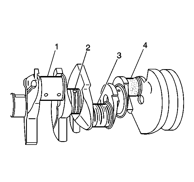
- Inspect the crankshaft journals (1) for wear. The journals should be smooth with no signs of scoring, wear, or damage.
- Inspect the crankshaft journals for grooves and scoring (2).
- Inspect the crankshaft journals for roughness and scratches (3).
- Inspect the crankshaft journals for pitting or imbedded bearing material (4). Inspect the corresponding bearing inserts for imbedded foreign material. If foreign material exists, find the cause and repair it.
- Inspect the crankshaft bearings for craters or pockets. Flattened sections on the bearing halves also indicate fatigue.
- Inspect the crankshaft bearings for excessive scoring or discoloration--overheating.
- Inspect the crankshaft bearings for dirt or debris imbedded into the bearing material.
- Inspect the crankshaft bearings for improper seating indicated by bright, polished sections of the bearing.
- Measure the crankshaft connecting rod and main bearing journals for out-of-round.
- Measure the crankshaft journals for taper.
- Regrind or replace the crankshaft if the above measurements exceed specifications.
- Note the location of the main bearing high spots. If they are not in line, the crankshaft is bent and must be replaced.
- Measure the crankshaft runout.
- Measure the crankshaft runout at the center journal using the J 7872 .
- Replace the crankshaft if the measurements exceed specifications.
- Measure the flywheel face runout using a J 8001 with a J 26900-13 .
- Replace or repair the flywheel if the runout exceeds specifications.
- Measure the crankshaft end play using the J 7872 .
- The crankshaft thrust bearing (1) is available in standard and oversized.
- If the end play exceeds the maximum replace the thrust bearing with a new standard size thrust bearing. If the end play still exceeds the maximum replace the thrust bearing with a new oversize thrust bearing.
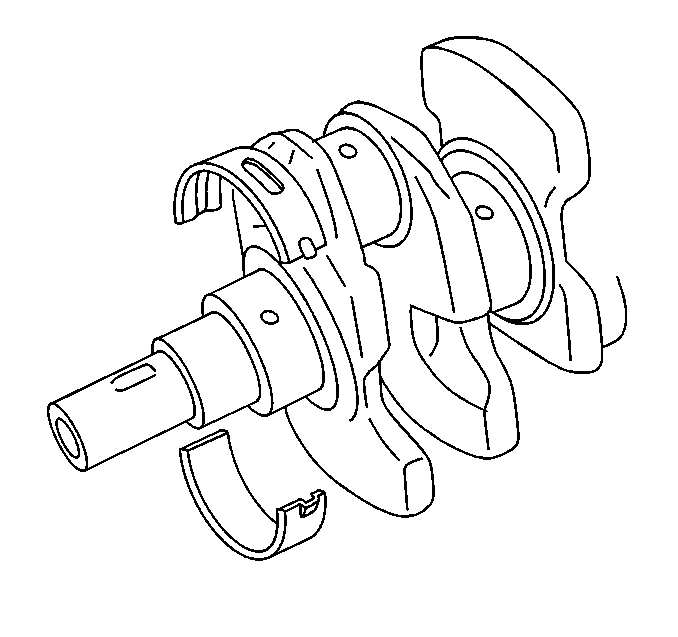
Caution: Refer to Safety Glasses Caution in the Preface section.
Important: Replace the crankshaft if cracks, severe gouges or burned spots are found. Slight roughness may be removed with a fine polishing cloth soaked in clean engine oil. Burrs may be removed with a fine oil stone.
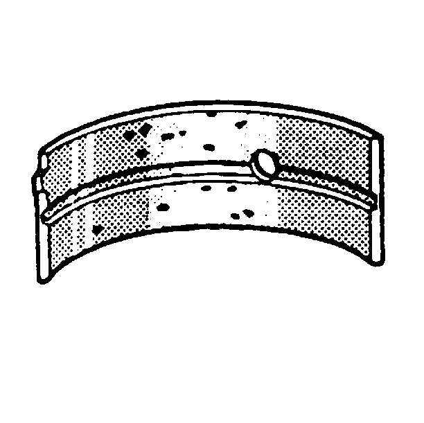
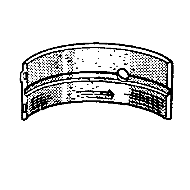
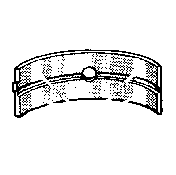
If the lower half of the bearing is worn or damaged, replace both upper and lower halves.
Generally, if the lower half is suitable for use, the upper half should also be suitable for use.
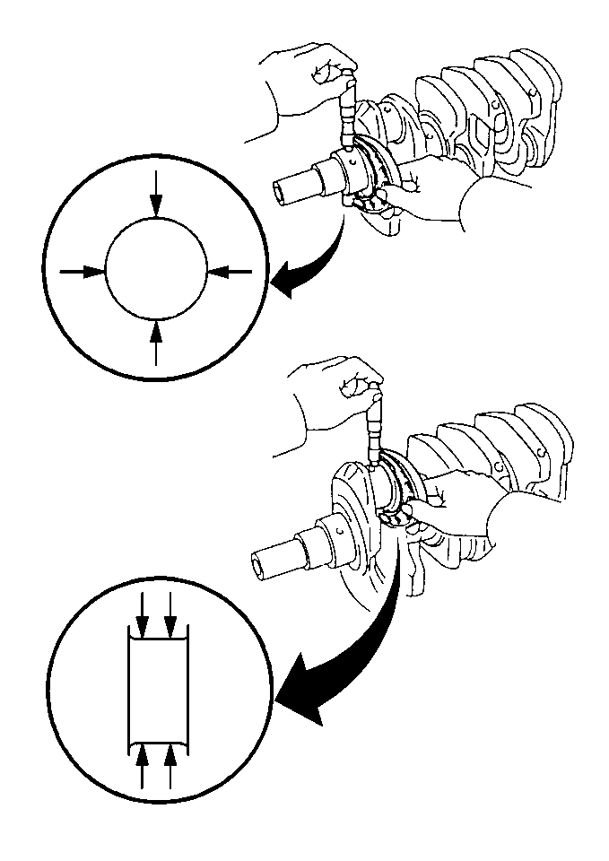
Measure each journal in 2 places 90 degrees apart. The difference between these 2 measurements is the out-of-round of the journal.
Maximum Out-of-Round
0.01 mm (0.0004 in)
Measure the journal at each end of the journal. The difference between these 2 measurements is the taper of the journal.
Maximum Taper
0.01 mm (0.0004 in)
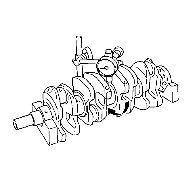
Support the crankshaft on the front and rear journals using wooden V blocks.
Maximum Runout
0.06 mm (0.0023 in)
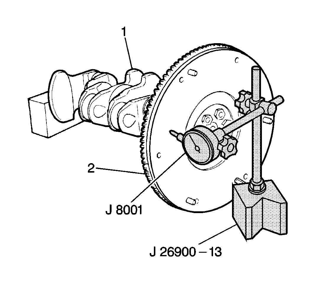
Maximum Runout
0.2 mm (0.0078 in)
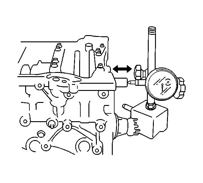
Important: The lower crankcase must be installed and properly torqued in order to measure crankshaft end play.
Standard Crankshaft End Play
0.11-0.31 mm (0.0044-0.0122 in)
Maximum Crankshaft End Play
0.38 mm (0.0149 in)
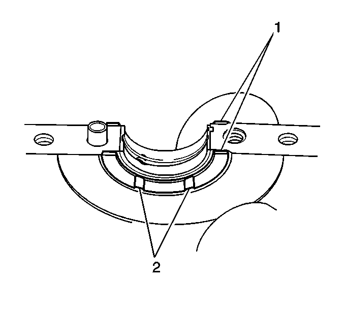
Standard Thrust Bearing Thickness
2.500 mm (0.984 in)
0.125 mm (0.0049 in) Oversize Thrust Bearing Thickness
2.563 mm (0.1009 in)
Crankshaft Main Bearing Cap Bolts Cleaning and Inspection
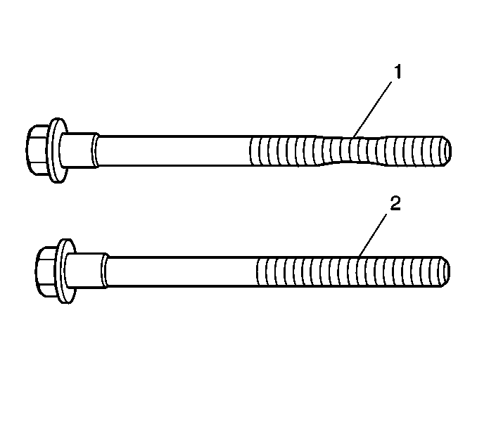
- Clean the main bearing cap bolts. Compare the main bearing cap bolts to a known good bolt (2) if necessary.
- Inspect the main bearing cap bolts for the following:
- Replace the main bearing cap bolts as necessary.
| • | Damaged threads |
| • | Stretching (1) |
| • | Damaged heads caused by improper use of tools |
Crankshaft Main Bearing Selection
- The crankshaft bearings are of the precision insert type. The crankshaft bearings are available in standard and 0.25 mm (0.0098 in) undersized. Undersized refers to crankshaft diameter. Both standard and undersized bearings are each available in 5 sizes (tolerances) differing in thickness in the center of the bearing. The upper bearing half has an oil groove, the lower bearing half does not have an oil groove.
- Inspect the crankshaft main bearing bores using the following procedure:
- Install the original crankshaft main bearing inserts on to the cylinder block and the lower crankcase assembly.
- Carefully place the crankshaft on to the bearing inserts in the cylinder block.
- Lay a piece of gauging plastic (1) across each crankshaft main journal (avoiding the oil hole).
- Carefully place the lower crankcase assembly on to the cylinder block.
- Install the 16 main bearing cap bolts (1-16). Progressively torque the main bearing cap bolts using 2 steps in the sequence shown.
- Install the 6 lower crankcase bolts. Progressively torque the lower crankcase bolts using 2 steps.
- Install the long lower crankcase bolt.
- After reaching the proper torque, remove the lower crankcase bolts and the crankshaft main bearing cap bolts.
- Carefully remove the lower crankcase assembly from the cylinder block.
- Measure the gauging plastic (1) at its widest point.
- A new standard bearing may produce the correct oil clearance. If not, regrind the crankshaft and install 0.25 mm (0.0098 in) undersized bearings.
- The crankweb is stamped with numbers. The numbers represent the corresponding journal diameter marked with an arrow. If using a standard bearing, replace it with one having the same color. If the color of the bearing cannot be determined, select the correct bearing by interpreting the numbers and letters imprinted on the cylinder block and crankshaft.
- The lower crankcase is stamped with letters. The letters represent the crankshaft bearing cap bore diameter without the bearings installed.
- There are 5 standard bearings available. The bearings differ in thickness at the center of the bearing. Each bearing is marked with paint (1). The color of the paint indicates the thickness of the bearing.
- Refer to the standard main bearing selection table in Engine Mechanical Specifications . Using the intersection of the letters and numbers, select the correct bearing from the table. Measure the oil clearance. If the oil clearance is incorrect install the next thicker bearing and recheck the oil clearance.
Notice: Do not shim, scrape, or file bearing inserts. Do not touch the bearing surface of the insert with bare fingers. Skin oil and acids will etch the bearing surface.

Important: If crankshaft bearing failure is due to other than normal wear, investigate the cause. Inspect the crankshaft bearing bores.
| 2.1. | Tighten the lower crankcase cap to specification. |
| 2.2. | Measure the bearing bore for taper and out-of-round. |
| 2.3. | No taper or out-of-round should exist. |
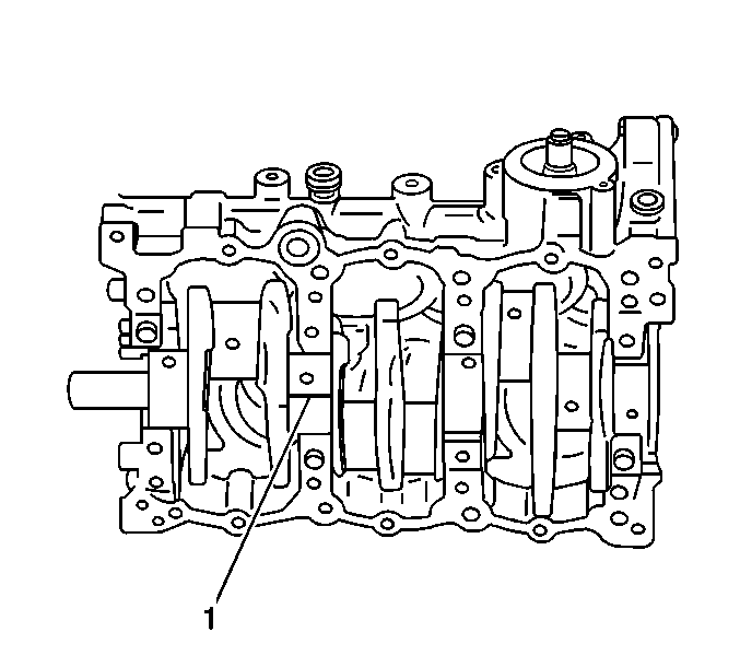
Important: Do not turn the crankshaft while measuring the bearing clearance.
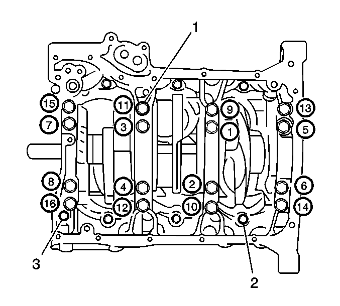
Notice: Use the correct fastener in the correct location. Replacement fasteners must be the correct part number for that application. Fasteners requiring replacement or fasteners requiring the use of thread locking compound or sealant are identified in the service procedure. Do not use paints, lubricants, or corrosion inhibitors on fasteners or fastener joint surfaces unless specified. These coatings affect fastener torque and joint clamping force and may damage the fastener. Use the correct tightening sequence and specifications when installing fasteners in order to avoid damage to parts and systems.
1st Pass
Tighten the main bearing cap bolts to 42 N·m (31 lb ft).
2nd Pass
Tighten the main bearing cap bolts to 60 N·m (43.5 lb ft).
1st Pass
Tighten the 6 lower crankcase bolts to 19 N·m (14 lb ft)
2nd Pass
Tighten the 6 lower crankcase bolts to 27 N·m (19.5 lb ft)
1st Pass
Tighten the long lower crankcase bolt to 27 N·m (19.5 lb ft)
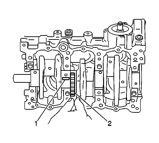
Standard Oil Clearance:
0.024-0.044 mm (0.0009-0.0017 in)
Maximum Oil Clearance:
0.060 mm (0.0023 in)
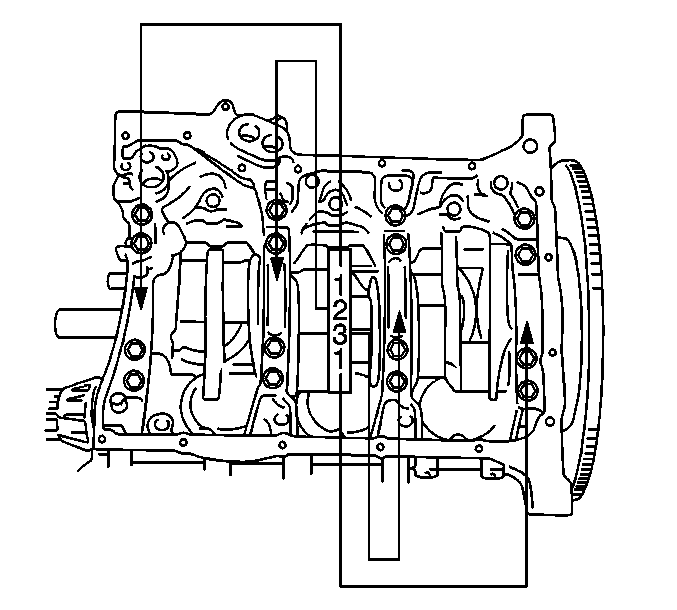
| • | Number 1 represents a journal diameter of 64.994-65.000 mm (2.5588-2.5590 in). |
| • | Number 2 represents a journal diameter of 64.988-64.994 mm (2.5586-2.5588 in). |
| • | Number 3 represents a journal diameter of 64.982-64.988 mm (2.5583-2.5586 in). |
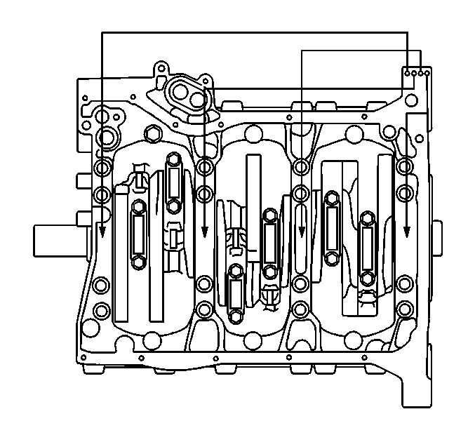
| • | Letter A represents a crankshaft bearing cap bore diameter of 70.000-70.006 mm (2.7559-2.7561 in). |
| • | Letter B represents a crankshaft bearing cap bore diameter of 70.006-70.012 mm (2.7561-2.7563 in). |
| • | Letter C represents a crankshaft bearing cap bore diameter of 70.012-70.018 mm (2.7563-2.7566 in). |
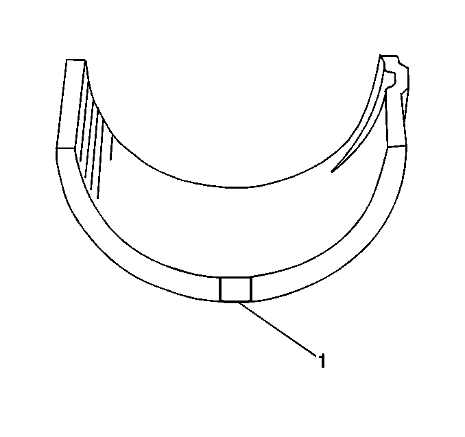
| • | Black paint indicates a bearing thickness of 2.496-2.500 mm (0.0983-0.0984 in). |
| • | No paint, colorless, indicates a bearing thickness of 2.499-2.503 mm (0.0984-0.0985 in). |
| • | Yellow paint indicates a bearing thickness of 2.502-2.506 mm (0.0985-0.0986 in). |
| • | Blue paint indicates a bearing thickness of 2.505-2.509 mm (0.0986-0.0987 in). |
| • | Pink paint indicates a bearing thickness of 2.508-2.512 mm (0.0987-0.0989 in). |
Undersized Main Bearing Selection
- If new standard bearings do not produce the correct oil clearance, regrind the crankshaft to a finished diameter of 64.732-64.750 mm (2.5485-2.5492 in) and install 0.25 mm (0.0098 in) undersized bearings. Undersized bearings are available in 5 sizes, tolerances, differing in thickness in the center of the bearing.
- Undersized bearings are distinguished from standard size bearings by a double paint mark (1).
- Measure the reground crankshaft journals for out-of-round.
- Measure the reground crankshaft journals for taper.
- Measure the reground crankshaft journals for size.
- Refer to the undersized main bearing selection table in Engine Mechanical Specifications . Using the intersection of the measured journal size and the letters on the lower crankcase select the correct sized bearing from the table. Measure the oil clearance. If the oil clearance is incorrect, install the next thicker bearing and recheck the oil clearance.
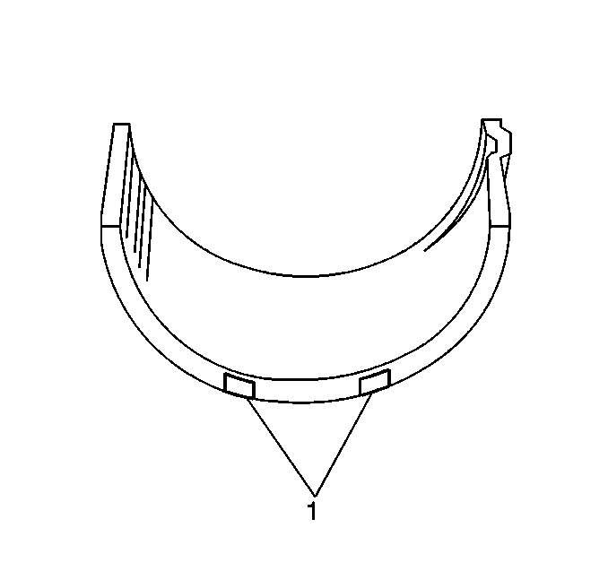
| • | Black and red paint indicates a bearing thickness of 2.621-2.625 mm (0.1032-0.1033 in). |
| • | Red paint only indicates a bearing thickness of 2.624-2.628 mm (0.1033-0.1034 in). |
| • | Yellow and red paint indicates a bearing thickness of 2.627-2.631 mm (0.1034-0.1035 in). |
| • | Blue and red paint indicates a bearing thickness of 2.630-2.634 mm (0.1035-0.1036 in). |
| • | Pink and red paint indicates a bearing thickness of 2.633-2.637 mm (0.1037-0.1038 in). |

Maximum Out-of-Round
0.01 mm (0.0004 in)
Maximum Taper
0.01 mm (0.0004 in)
