Removal Procedure
- Disconnect the negative battery cable. Refer to
Battery Negative Cable Disconnection and Connection
in Engine
Electrical.
- Remove the console. Refer to
Front Floor Console Replacement
in Instrument Panel, Gages and Console.
- Remove the knee bolster.
- Loosen the lower steering column bracket bolts.
- Lower the steering column.
- Place the transmission shift lever in the PARK position.
Important: Do not proceed to the next step with the key in any position other than
the RUN position.
- Turn the ignition key to the RUN position.

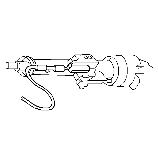
- Insert a screwdriver blade
into the slot provided in the ignition switch inhibitor.
- Depress the cable latch. Pull the control cable from the inhibitor.

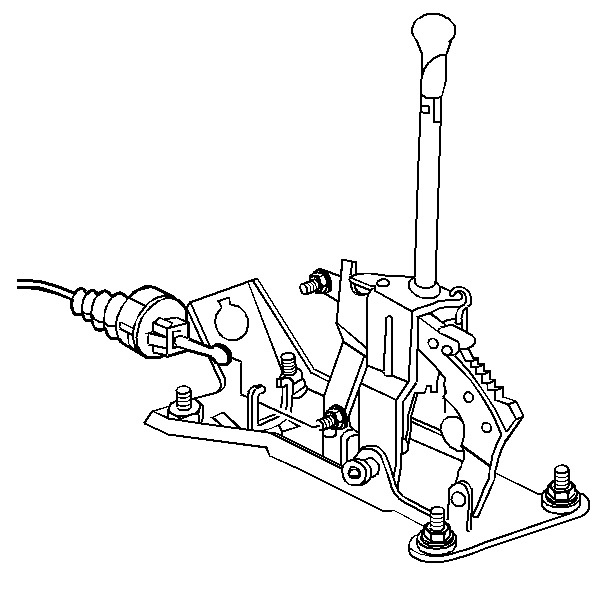
- Push the cable connector
lock button at the shifter base to the up position.
- Unsnap the cable from the park/lock lever pin.
- Depress the two cable latches. Remove the control cable latches
from the automatic transmission control.
- Remove the control cable clips.
Installation Procedure

Important: When installing a new park/lock cable, keep the shipping cover gauge
attached until you are instructed to detach it. The shipping cover gauge will
aid in the proper positioning of the cable.
- Ensure that the cable lock button is in the up position. Place the shift
lever in the PARK position.
- Snap the control cable connector into the automatic transmission
control.
- Place the ignition key in the RUN position.

Important: Do not insert the cable with the key in any position other than the
RUN position.
- Snap the control cable into the inhibitor housing until the snap lock
is seated.
- Remove the shipping cover gauge.
- Turn the key to the LOCK position.

- Snap the control cable
end onto the shift park/lock lever pin.
- Push the cable connector hose forward in order to remove any slack.
- With no load applied to the connector nose, snap the cable connector
lock button down.

Important: Inspect for proper operation of the park/lock control cable before installing
the steering column to the instrument panel.
- Raise and connect the steering column.
- Tighten the lower steering column bracket bolts.
- Install the knee bolster.
- Install the console. Refer to
Front Floor Console Replacement
in Instrument Panel, Gages and Console
- Connect the negative battery cable. Refer to
Battery Negative Cable Disconnection and Connection
in Engine
Electrical.
Inspection Procedure
Important:
| • | There must be no gap between the metal terminal stop and the protruding
end of the white plastic collar. If there is a gap between the terminal stop
and the collar, adjust the position of the park lock cable. |
| • | The white plastic collar must be flush or recessed about 1 mm
(0.04 in) within the ignition park lock housing. If the white plastic
collar is not in the proper location, adjust the position of the park lock
cable. |
- Ensure that the terminal stop on the column end of the park/lock cable
is touching the white collar that protrudes from the ignition switch. Complete
the following steps in order to inspect:
| 1.1. | Turn the column lock cylinder to the LOCK position. |
| 1.2. | Place the floor shift lever into the PARK position. |
| 1.3. | Verify the correct position of the terminal stop. |
- Ensure that the white plastic collar travel does not exceed 1.5 mm
(0.06 in). In order to inspect the white plastic collar travel, complete
the following steps:
| 2.1. | Ensure that the column lock cylinder remains in the Lock position. |
| 2.2. | Ensure that the floor shift lever remains in the PARK position. |
| 2.3. | Gently depress the park/lock button on the floor shift lever until
resistance is felt. |
| 2.4. | Inspect that the white plastic collar travels no more than 1.5 mm
(0.06 in). The floor shift lever must not come out of PARK. |
- With the column lock cylinder On, verify proper movement of the
floor shift lever through all of the gear selections.
- While moving the floor shift lever through all of the drive gears,
verify that the column lock cylinder cannot be turned to the Lock position.
- Ensure that the key can be removed with the column lock cylinder
in the Lock position and the floor shift lever in the PARK position.
Important: There are 5 inspections that verify proper installation. The installation
must pass all 5 tests.
- Adjust the park/lock cable.


