Water Pump Replacement 2.2L
Removal Procedure
- Drain the cooling system. Refer to Cooling System Draining and Filling .
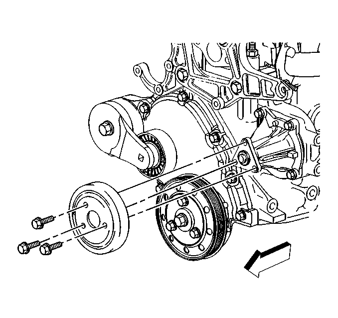
- Loosen the coolant pump pulley bolts.
- Remove the accessory drive belt. Refer to Drive Belt Replacement in Engine Mechanical - 2.2L.
- Remove the coolant pump pulley bolts.
- Remove the coolant pump pulley.
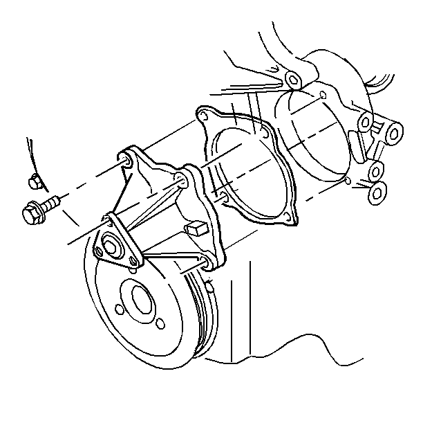
- Remove the coolant pump bolts.
- Remove the coolant pump and the gasket.
- Completely clean the sealing surfaces of the coolant pump and the engine block.
Installation Procedure
- Using a new gasket, install the coolant pump and the attaching bolts. Coat the bolt threads with pipe sealant GM P/N 12346004 (Canadian P/N 10953480), or equivalent.
- Install the coolant pump pulley and bolts.
- Install the accessory drive belt. Refer to Drive Belt Replacement in Engine Mechanical - 2.2L.
- Refill the cooling system. Refer to Cooling System Draining and Filling .
- Start the engine. After the engine reaches normal operating temperature, check for coolant leaks.

Notice: Use the correct fastener in the correct location. Replacement fasteners must be the correct part number for that application. Fasteners requiring replacement or fasteners requiring the use of thread locking compound or sealant are identified in the service procedure. Do not use paints, lubricants, or corrosion inhibitors on fasteners or fastener joint surfaces unless specified. These coatings affect fastener torque and joint clamping force and may damage the fastener. Use the correct tightening sequence and specifications when installing fasteners in order to avoid damage to parts and systems.
Tighten
Tighten the coolant pump bolts to 25 N·m (18 lb ft).

Tighten
Tighten the coolant pump pulley bolts to 30 N·m (22 lb ft).
Water Pump Replacement 2.4L
Removal Procedure
- Drain the cooling system. Refer to Cooling System Draining and Filling .
- Remove the exhaust manifold. Refer to Exhaust Manifold Replacement in Engine Exhaust.
- Remove the coolant outlet pipe. Refer to Radiator Outlet Pipe Replacement .
- Disconnect the heater hose quick connect from the heater outlet pipe.
- Remove the timing chain and tensioner. Refer to Camshaft Timing Chain, Sprocket, and Tensioner Replacement in Engine Mechanical.
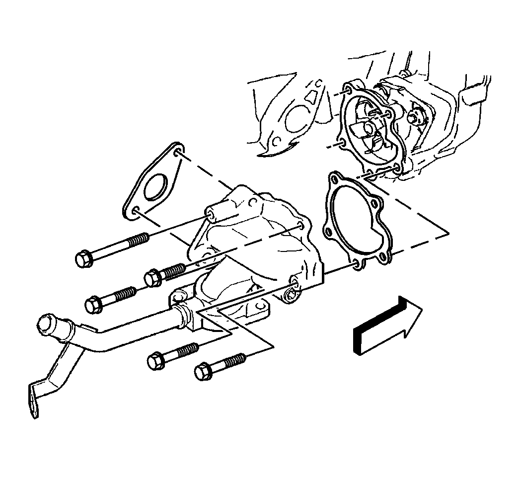
- Remove the water pump cover-to-cylinder block bolts.
- Remove water pump cover pipe bracket bolt (Bellhousing bolt).
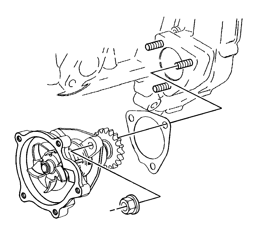
- Remove the water pump-to-timing chain housing nuts.
- Remove the water pump and cover assembly.
- Remove the water pump cover-to-coolant pump assembly bolts.
- Clean all sealing surfaces.
Installation Procedure
- Install the water pump cover to the water pump assembly.
- Install the pump cover bolts. Hand tighten the bolts.
- Install water pump/cover assembly.
- Install the cover-to-block bolts. Hand tighten the bolts.
- Install the coolant pump-to-timing chain housing nuts. Hand tighten the nuts.
- Install water pump cover pipe bolt (Bellhousing Bolt).
- Torque in sequence as follows:
- Install heater hose to water pump cooling pipe.
- Install radiator outlet pipe.Refer to Radiator Outlet Pipe Replacement .
- Install the exhaust manifold and install new gaskets. Refer to Exhaust Manifold Replacement in Engine Exhaust.
- Install oil level indicator tube and indicator.
- Connect the brake vacuum pipe to the cam housing.
- Raise the vehicle. Refer to Lifting and Jacking the Vehicle in General Information.
- Install catalytic converter. Refer to Catalytic Converter Replacement in Engine Exhaust.
- Install the timing chain and tensioner. Refer to Camshaft Timing Chain, Sprocket, and Tensioner Replacement in Engine Mechanical - 2.4 L.
- Lower the vehicle.
- Fill the cooling system. Refer to Cooling System Draining and Filling .
- Inspect the system for leaks.
Important: Before you install the coolant pump, read the entire procedure. Follow the tightening sequences in order to avoid part damage and to provide proper sealing.


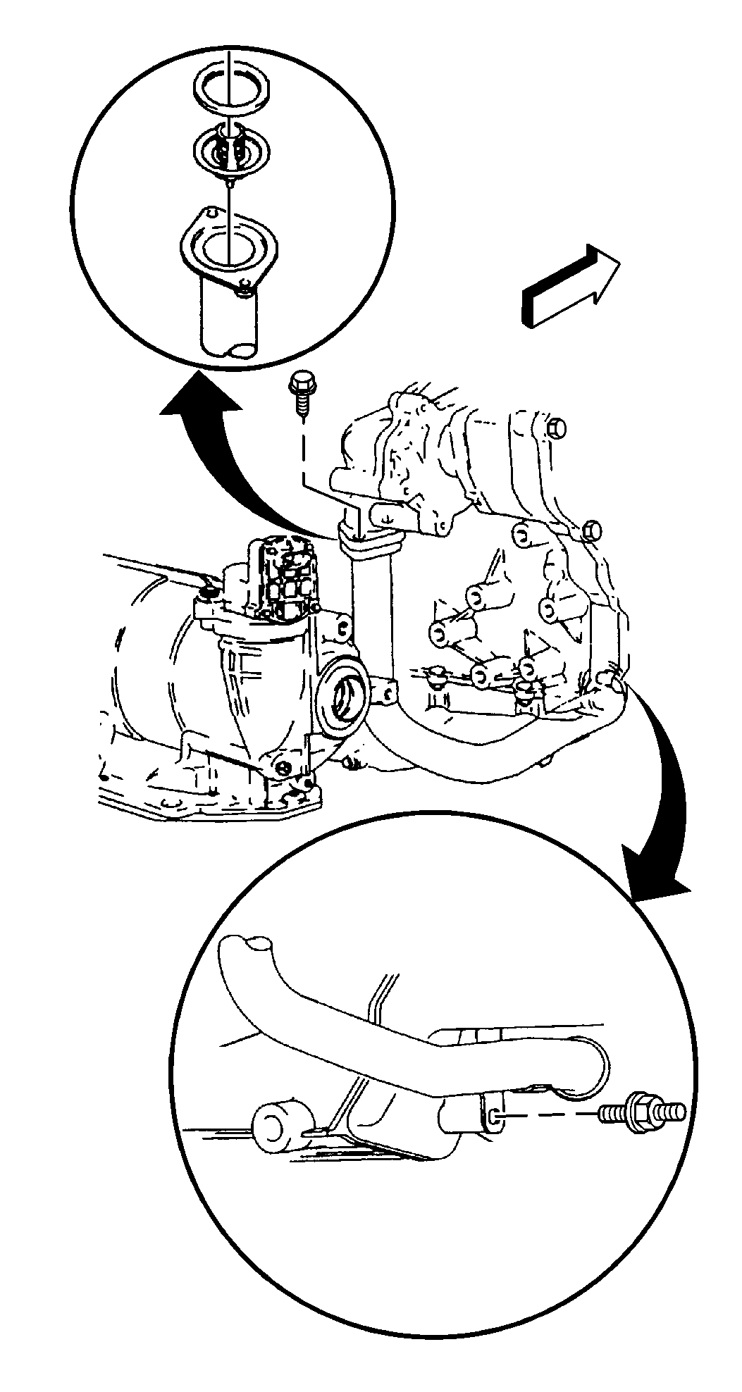
Notice: Use the correct fastener in the correct location. Replacement fasteners must be the correct part number for that application. Fasteners requiring replacement or fasteners requiring the use of thread locking compound or sealant are identified in the service procedure. Do not use paints, lubricants, or corrosion inhibitors on fasteners or fastener joint surfaces unless specified. These coatings affect fastener torque and joint clamping force and may damage the fastener. Use the correct tightening sequence and specifications when installing fasteners in order to avoid damage to parts and systems.
| 7.1. | Tighten the pump assembly-to-timing chain housing nuts. |
Tighten
Tighten nuts to 26 N·m (19 lb ft).
| 7.2. | Tighten the pump cover-to-pump assembly bolts. |
Tighten
Tighten the bolts to 14 N·m (10 lb ft).
| 7.3. | Tighten the coolant pump cover-to-engine block bolts. Tighten the bottom bolt first. |
Tighten
Tighten bolts to 26 N·m (19 lb ft).
Water Pump Replacement 2.2L - L61
Tools Required
J 43651 Water Pump Holding Tool
Removal Procedure
- If equipped with an automatic transmission, remove the exhaust manifold. Refer to Exhaust Manifold Removal in Engine Mechanical - 2.2L (L61).
- Drain the cooling system. Refer to Cooling System Draining and Filling .
- Raise and suitably support the vehicle. Refer to Lifting and Jacking the Vehicle in General Information.
- Remove the right front tire and wheel. Refer to Tire and Wheel Removal and Installation in Tires and Wheels.
- Remove the front fender liner. Refer to Front Fender Liner Replacement in Body Front End.
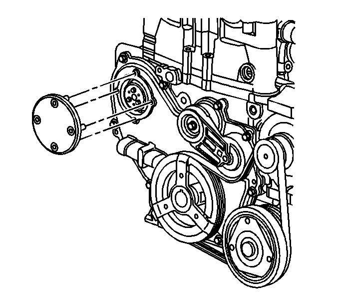
- Remove the access plate on the water pump sprocket from the timing cover.
- Install J 43651 to the water pump sprocket.
- Use the access plate bolts to secure J 43651 to the engine front cover.
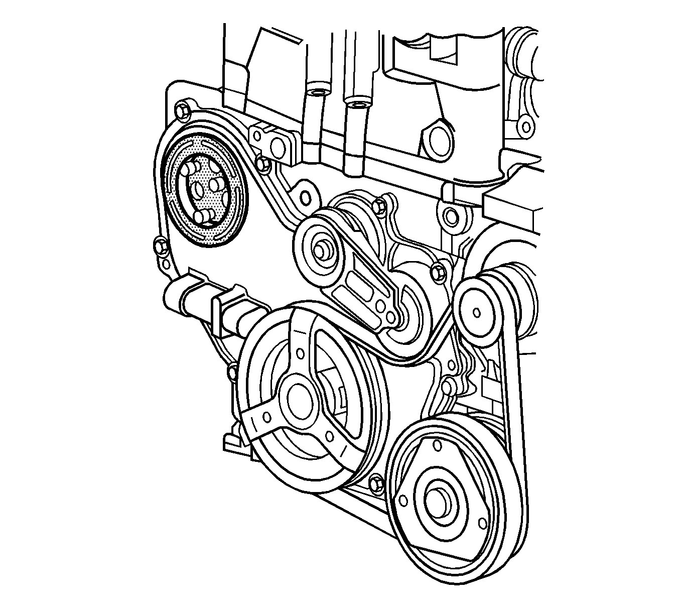
- Remove the bolts that secure the sprocket to the water pump.
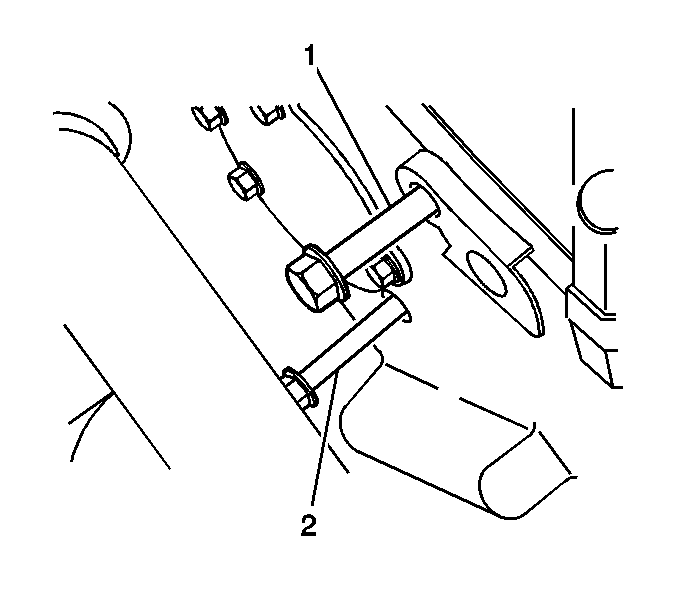
- Remove the bolt (1) that secures the engine block to the water pump.
- Remove the bolt (2) that secures the engine front cover to the water pump.
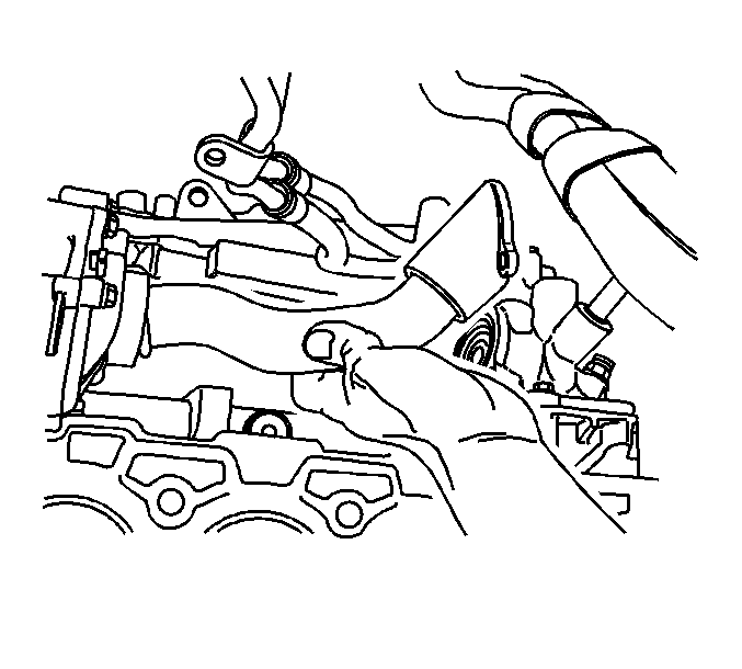
- Remove the feed pipe that joins the thermostat housing to the water pump.
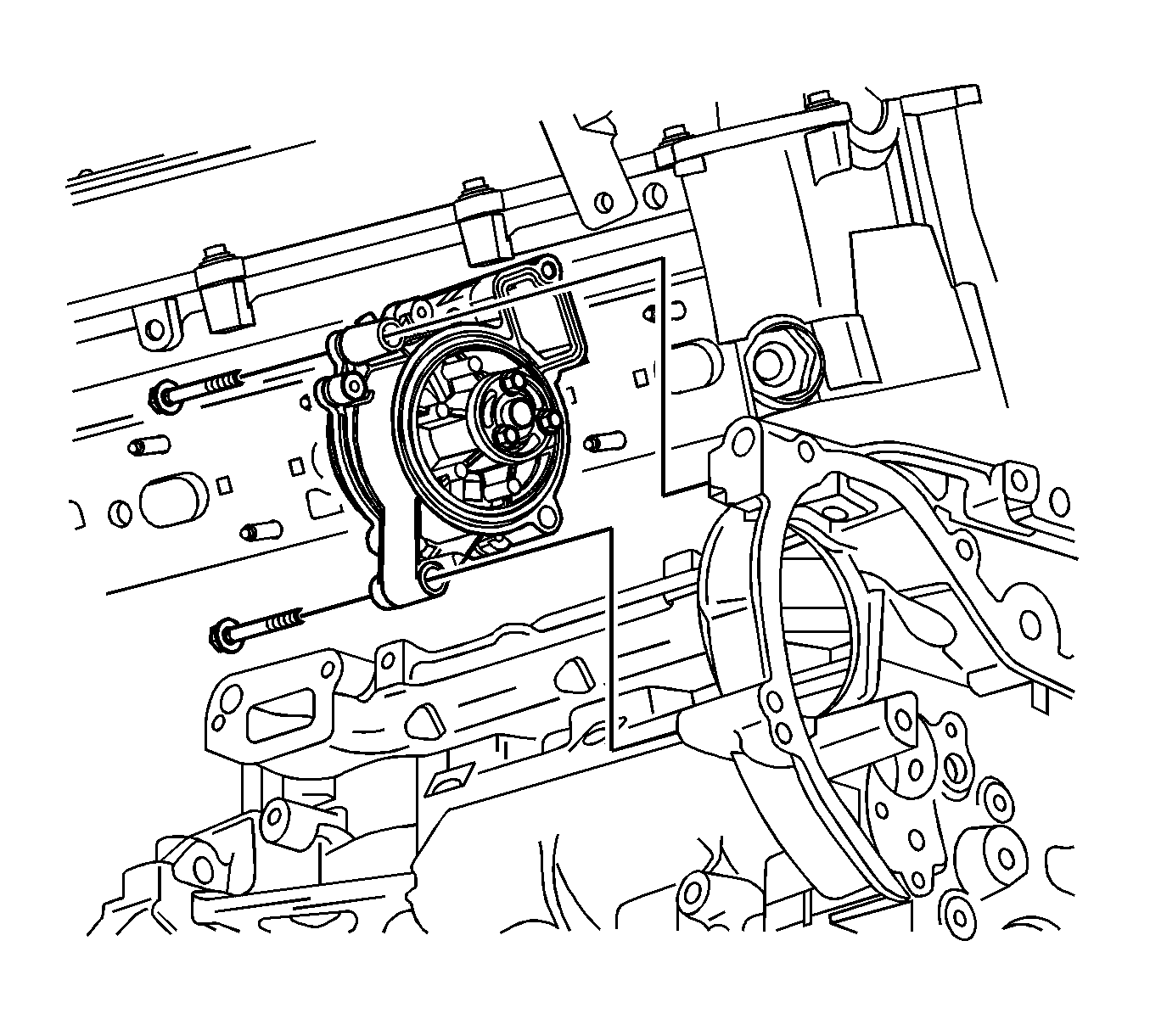
- Remove the 2 bolts that secure the water pump to the engine block.
- Remove the water pump.
Installation Procedure
- Use a threaded stud in the hub to align the hub to the water pump sprocket.
- Install the water pump.
- Install the 2 bolts that secure the water pump to the engine block.
- Install the feed pipe that joins the thermostat housing to the water pump. Refer to Engine Coolant Thermostat Replacement .
- Install the engine front cover bolt (2) and the bolt (1) that secures the engine block to the water pump.
- Install 2 of the bolts that secure the water pump sprocket to the water pump.
- Remove the threaded stud.
- Install the last bolt.
- Remove J 43651 .
- Install the access plate on the water pump sprocket to the timing cover.
- Install the bolts that secure the access plate to the timing cover.
- Install the front fender liner. Refer to Front Fender Liner Replacement in Body Front End.
- Install the right front tire and wheel. Refer to Tire and Wheel Removal and Installation in Tires and Wheels.
- If equipped with an automatic transmission, install the exhaust manifold. Refer to Exhaust Manifold Installation in Engine Mechanical - 2.2L (L61).
- Fill the cooling system. Refer to Cooling System Draining and Filling .

Notice: Refer to Fastener Notice in the Preface section.
Tighten
Tighten the bolts to 20 N·m (15 lb ft).


Tighten
Tighten the bolts to 20 N·m (15 lb ft).
Tighten
Tighten the bolts to 10 N·m (89 lb in).


Tighten
Tighten the bolts to 10 N·m (89 lb in).
