Air Conditioning Compressor Replacement L61
Removal Procedure
- Recover the refrigerant. Refer to Refrigerant Recovery and Recharging .
- Remove the drive belt. Refer to Drive Belt Replacement in Engine Mechanical-2.2L (L61).
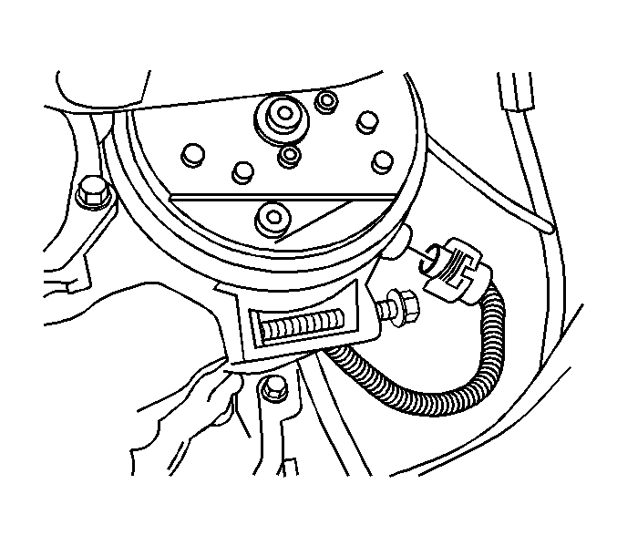
- Disconnect the electrical connector from the compressor.
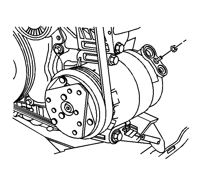
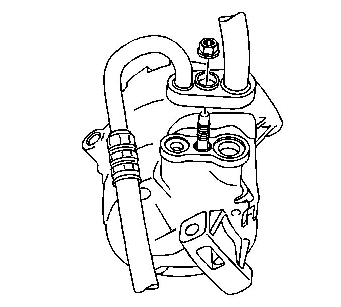
- Remove the bolt holding the compressor hose assembly to the compressor.
- Remove the hose assembly from the compressor.
- Remove and discard the sealing washers.
- Remove the compressor mounting bolts.
- Remove the compressor.
- If replacing the compressor, drain and measure as much of the oil from the compressor as possible using the following procedure:
| 9.1. | Drain the oil from both the suction and the discharge ports into a clean container. |
| 9.2. | Remove the compressor crankcase oil drain plug and drain the crankcase oil into the same container. |
| 9.3. | Measure and record the amount of oil drained from the compressor. This measurement will be used during the compressor installation procedure. |
| 9.4. | Properly discard the used PAG oil. |
Installation Procedure
- Drain the PAG oil from the new compressor into the clean calibrated measuring container. Drain from the crankcase and from the rear head ports.
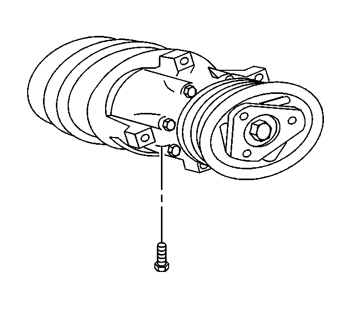
- Install the crankcase oil drain bolt to the compressor.
- Rotate the clutch driver 3 times to lubricate the internal swashplate and the piston shoes.
- Install the bolts and the compressor to the engine.
- Install NEW sealing washers on the compressor ports. Refer to Sealing Washer Replacement .
- Install the compressor hose assembly .
- Install the compressor hose assembly nut.
- Connect the compressor electrical connector.
- Install the drive belt. Refer to Drive Belt Replacement in Engine Mechanical-2.2L (L61).
- Lower the vehicle.
- Evacuate and charge the refrigerant system. Refer to Refrigerant Recovery and Recharging .
Notice: Do not mix refrigerant oils. Use of incorrect refrigerant oil will cause compressor failure.
The CVC compressor uses a low viscosity refrigerant oil, GM P/N 12378526 (Canadian P/N 88900060).Important: NEW CVC compressor assemblies are shipped with a full poly-alkylene glycol (PAG) refrigerant oil charge. Use of the incorrect PAG oil can result in compressor failure.
| • | If the amount of old oil drained is less than or equal to 75 ml (2.5 oz), add 75 ml of new oil into the new compressor through the crankcase bolt hole. |
| • | If the amount of old oil drained is greater than 75 ml (2.5 oz), add the equivalent amount of new oil into the new compressor through the crankcase bolt hole. Refer to Refrigerant System Capacities . |

Notice: Use the correct fastener in the correct location. Replacement fasteners must be the correct part number for that application. Fasteners requiring replacement or fasteners requiring the use of thread locking compound or sealant are identified in the service procedure. Do not use paints, lubricants, or corrosion inhibitors on fasteners or fastener joint surfaces unless specified. These coatings affect fastener torque and joint clamping force and may damage the fastener. Use the correct tightening sequence and specifications when installing fasteners in order to avoid damage to parts and systems.
Tighten
Tighten the drain bolt to 16 N·m (12 lb ft).
Tighten
Tighten the bolts to 22 N·m (16 lb ft).

Tighten
Tighten the nut to 16 N·m (12 lb ft).
Air Conditioning Compressor Replacement LN2
Tools Required
J 39400-A Halogen Leak Detector
Removal Procedure
- Recover the refrigerant. Refer to Refrigerant Recovery and Recharging .
- Remove the drive belt. Refer to Drive Belt Replacement in Engine Mechanical-2.2L.
- Remove the right front fender liner. Refer to Front Fender Liner Replacement in Body Front End.
- Disconnect the compressor clutch electrical connector.
- Remove the bolt holding the compressor hose assembly to the compressor.
- Remove the hose assembly from the compressor.
- Remove and discard the sealing washers.
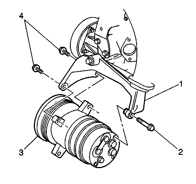
- Remove the compressor bolts (2,4).
- Remove the compressor (3).
- If replacing the same compressor, drain and measure as much of the oil from the compressor as possible using the following procedure:
| 10.1. | Drain the oil from both the suction and the discharge ports into a clean container. |
| 10.2. | Remove the compressor crankcase oil drain plug and drain the crankcase oil into the same container. |
| 10.3. | Measure and record the amount of oil drained from the compressor. This measurement will be used during the compressor installation procedure. |
| 10.4. | Properly discard the used PAG oil. |
Installation Procedure
- If a NEW A/C compressor is being installed, add 60 ml (2 oz), of PAG Oil to the compressor.
- Install the compressor crankcase oil drain bolt.
- Install the compressor (3) to the compressor mounting bracket (1).
- Install the compressor mounting bolts (4,2).
- Install NEW sealing washers to the compressor ports. Refer to Sealing Washer Replacement .
- Install the compressor hose assembly to the compressor.
- Install the bolt holding the compressor hose assembly to the compressor.
- Connect the clutch electrical connector.
- Install the right front fender liner. Refer to Front Fender Liner Replacement in Body Front End.
- Install the drive belt. Refer to Drive Belt Replacement in Engine Mechanical-2.2L.
- Evacuate and recharge the A/C system. Refer to Refrigerant Recovery and Recharging .
- Leak test the fittings of the component usingJ 39400-A .
Important: NEW A/C compressors are shipped WITHOUT poly-alkylene glycol (PAG) oil. Use of the incorrect PAG oil can result in compressor failure.
Notice: Use the correct fastener in the correct location. Replacement fasteners must be the correct part number for that application. Fasteners requiring replacement or fasteners requiring the use of thread locking compound or sealant are identified in the service procedure. Do not use paints, lubricants, or corrosion inhibitors on fasteners or fastener joint surfaces unless specified. These coatings affect fastener torque and joint clamping force and may damage the fastener. Use the correct tightening sequence and specifications when installing fasteners in order to avoid damage to parts and systems.
Tighten
Tighten the drain bolt to 20 N·m (15 lb ft).

Tighten
| • | Tighten the front compressor mounting bolts (4) to 45 N·m (33 lb ft). |
| • | Tighten the rear compressor mounting bolt (2) to 65 N·m (45 lb ft). |
Tighten
Tighten the bolt to 33 N·m (24 lb ft).
Air Conditioning Compressor Replacement LD9
Tools Required
J 39400-A Halogen Leak Detector
Removal Procedure
- Recover the refrigerant. Refer to Refrigerant Recovery and Recharging .
- Remove the drive belt. Refer to Drive Belt Replacement in Engine Mechanical-2.4L.
- Remove the right front fender liner. Refer to Front Fender Liner Replacement in Body Front End.
- Disconnect the clutch electrical connector from the compressor.
- Remove the EVAP canister purge solenoid valve from the compressor mounting stud. Refer to Evaporative Emission Canister Purge Solenoid Valve Replacement in Engine Controls-2.4L.
- Remove the bolt holding the compressor hose assembly to the compressor.
- Remove the compressor hose assembly from the compressor.
- Remove and discard the sealing washers.
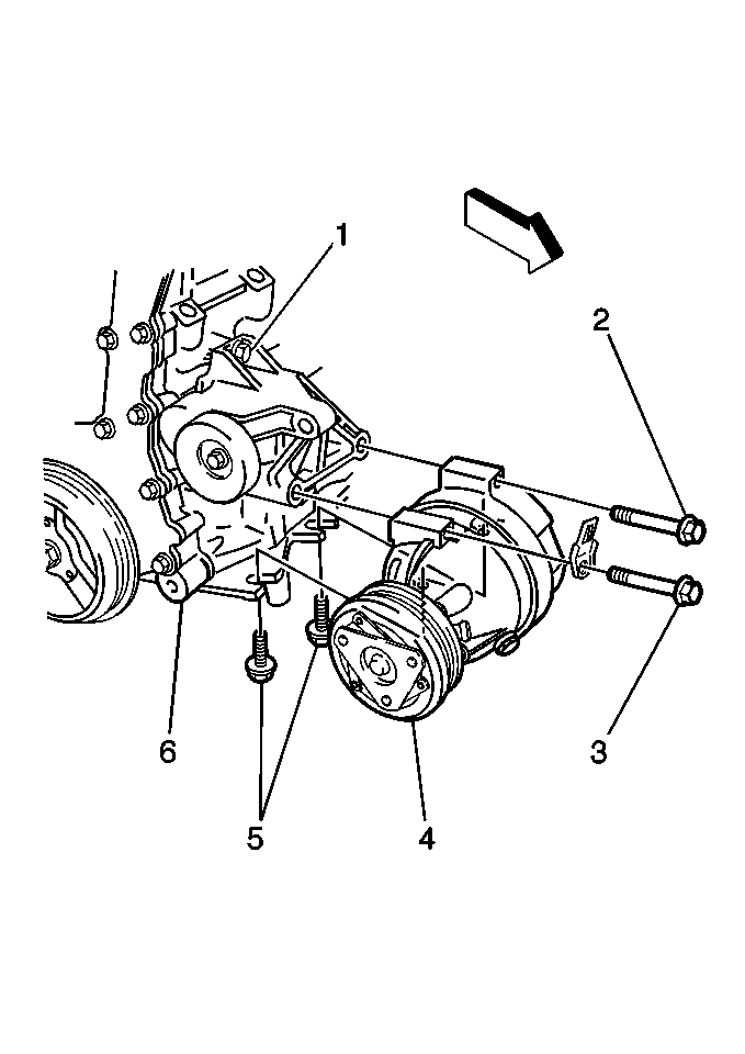
- Remove 2 bolts (5) holding the compressor to the oil pan.
- Remove the upper 2 mounting bolts (2,3).
- Remove the compressor.
- If replacing the same compressor, drain and measure as much of the oil from the compressor as possible using the following procedure:
| 12.1. | Drain the oil from both the suction and the discharge ports into a clean container. |
| 12.2. | Remove the compressor crankcase oil drain plug and drain the crankcase oil into the same container. |
| 12.3. | Measure and record the amount of oil drained from the compressor. This measurement will be used during the compressor installation procedure. |
| 12.4. | Properly discard the used PAG oil. |
Installation Procedure
- If a NEW A/C compressor is being installed, add 60 ml (2 oz) of PAG Oil to the compressor.
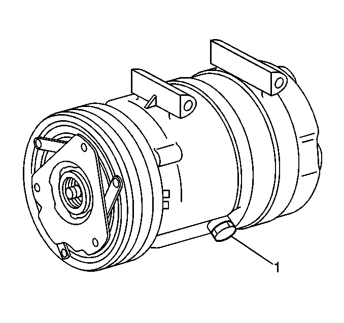
- Install the crankcase oil drain bolt (1) to the replacement compressor.
- Install the compressor (4) and loosely install the upper 2 compressor mounting bolts (2,3).
- Loosely install the 2 oil pan to compressor bolts (5).
- Tighten the mounting bolts to 50 N·m (37 lb ft).
- Tighten the oil pan bolts to 50 N·m (37 lb ft).
- Connect the clutch electrical connector.
- Install NEW sealing washers to the compressor ports.Refer to Sealing Washer Replacement
- Install the compressor hose assembly to the compressor.
- Install the bolt holding the compressor hose assembly to the compressor.
- Install the EVAP canister purge solenoid valve to the compressor mounting stud. Refer to Evaporative Emission Canister Purge Solenoid Valve Replacement in Engine Controls-2.4L.
- Install the right front fender liner. Refer to Front Fender Liner Replacement in Body Front End.
- Install the drive belt. Refer to Drive Belt Replacement in Engine Mechanical-2.4L.
- Evacuate and recharge the A/C system. Refer to Refrigerant Recovery and Recharging .
- Leak test the fittings of the component using J 39400-A .
Important: NEW A/C compressors are shipped WITHOUT poly-alkylene glycol (PAG) oil. Use of the incorrect PAG oil can result in compressor failure.
Notice: Use the correct fastener in the correct location. Replacement fasteners must be the correct part number for that application. Fasteners requiring replacement or fasteners requiring the use of thread locking compound or sealant are identified in the service procedure. Do not use paints, lubricants, or corrosion inhibitors on fasteners or fastener joint surfaces unless specified. These coatings affect fastener torque and joint clamping force and may damage the fastener. Use the correct tightening sequence and specifications when installing fasteners in order to avoid damage to parts and systems.
Tighten
Tighten the drain bolt to 20 N·m (15 lb ft).

Tighten
Tighten
Tighten the bolt to 33 N·m (24 lb ft).
