Removal Procedure
- Relieve the fuel system pressure. Refer to Fuel Pressure Relief .
- Remove the engine fuel supply and return pipes. Refer to Fuel Hose/Pipes Replacement - Engine Compartment .
- Remove the air cleaner outlet resonator. Refer to Air Cleaner Outlet Resonator Replacement .
- Disconnect the vent pipe from the fuel pressure regulator.
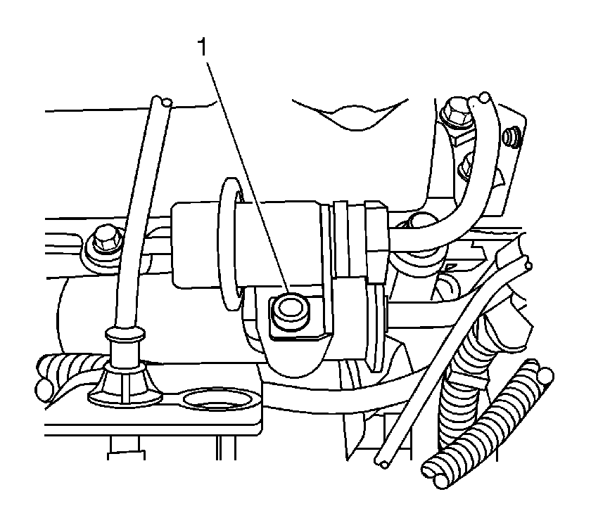
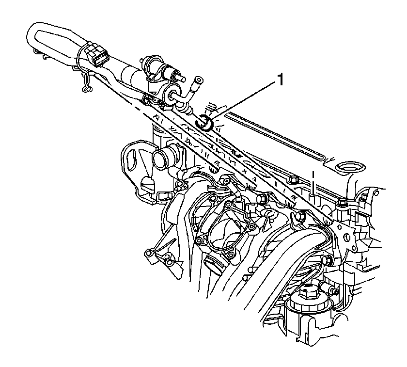
- Remove the fuel pressure regulator bolt (1).
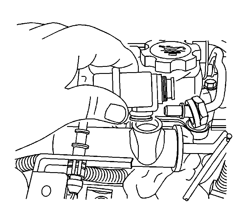
- Remove the fuel pressure regulator.
- Disconnect the fuel injector harness connectors.
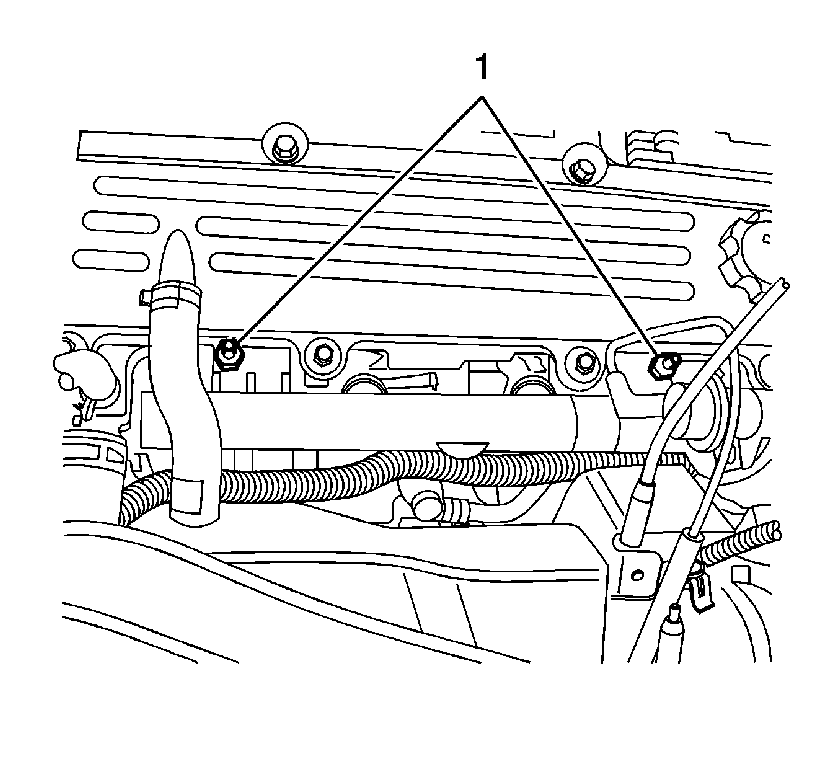
- Remove the fuel rail attaching studs (1).
- Remove the fuel rail using the following procedure:
- Remove the fuel injectors from the fuel rail. Refer to Fuel Injector Replacement .
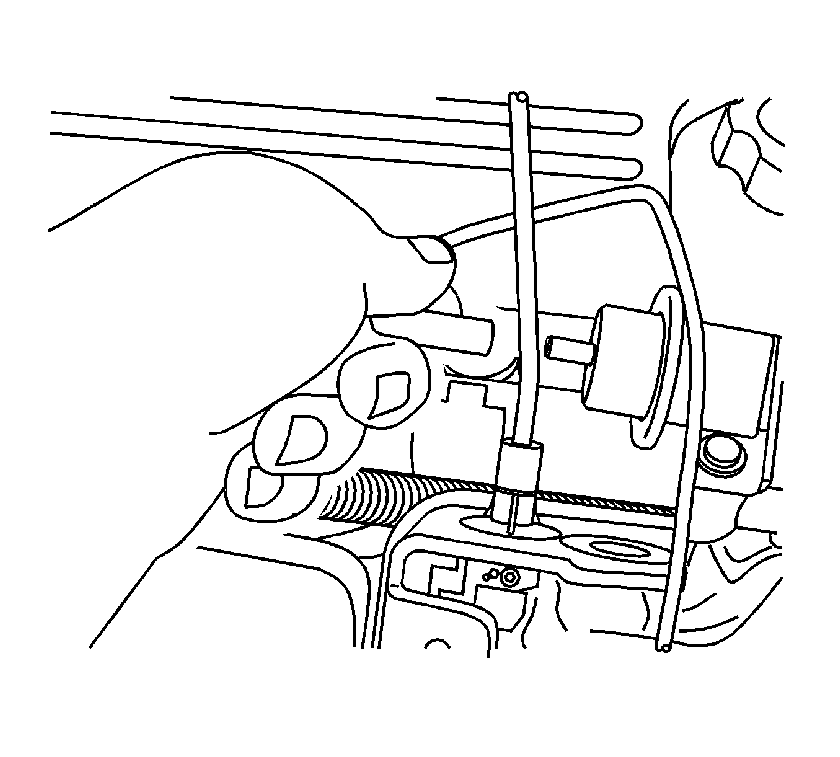
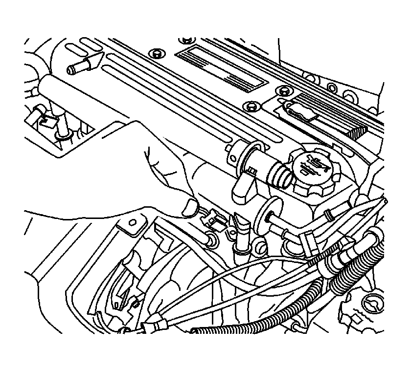
Important: Use care when removing the fuel rail assembly in order to prevent damage to the fuel injectors electrical connector terminals and spray tips.
| 9.1. | Pull the fuel rail back and upward to remove the fuel injectors from the cylinder head ports. |
| 9.2. | Rotate the fuel rail in order to position the injectors downward. |
| 9.3. | Remove the fuel rail. |
Installation Procedure
- If the fuel injector insulator cups (1) are removed from the cylinder head while removing the fuel rail, new insulator cups must be installed.
- Install the fuel injectors to the fuel rail. Refer to Fuel Injector Replacement .
- Install the fuel rail using the following procedure:
- Install the fuel rail attaching studs (1).
- Connect the fuel injector harness connectors. Pull back to insure the connectors are locked in place.
- Install the fuel supply and return pipes. Refer to Fuel Hose/Pipes Replacement - Engine Compartment .
- Install the fuel pressure regulator.
- Install the fuel pressure regulator bolt (1).
- Connect the vent pipe to the fuel pressure regulator.
- Install the air cleaner outlet resonator. Refer to Air Cleaner Outlet Resonator Replacement .
- Connect the negative battery cable. Refer to Battery Negative Cable Disconnection and Connection in Engine Electrical.
- Inspect for fuel leaks using the following procedure:

Important: Install new lower O-rings when reusing fuel injectors. Lubricate the injector tip O-rings prior to installing the injectors into the intake manifold.
| 3.1. | With the fuel injectors positioned downward, lower the fuel injectors into the cylinder head ports. |
| 3.2. | Align the injectors by rotating the fuel rail forward. |
| 3.3. | Carefully push the fuel injectors into the cylinder head ports. |
Notice: Use the correct fastener in the correct location. Replacement fasteners must be the correct part number for that application. Fasteners requiring replacement or fasteners requiring the use of thread locking compound or sealant are identified in the service procedure. Do not use paints, lubricants, or corrosion inhibitors on fasteners or fastener joint surfaces unless specified. These coatings affect fastener torque and joint clamping force and may damage the fastener. Use the correct tightening sequence and specifications when installing fasteners in order to avoid damage to parts and systems.
Tighten
Tighten the fuel rail studs to 10 N·m (89 lb in).


Tighten
Tighten the fuel pressure regulator bolt to 10 N·m (89 lb in).

| 12.1. | Turn ON the ignition, with the engine OFF for 2 seconds. |
| 12.2. | Turn OFF the ignition for 10 seconds. |
| 12.3. | Turn ON the ignition. |
| 12.4. | Inspect for fuel leaks. |
