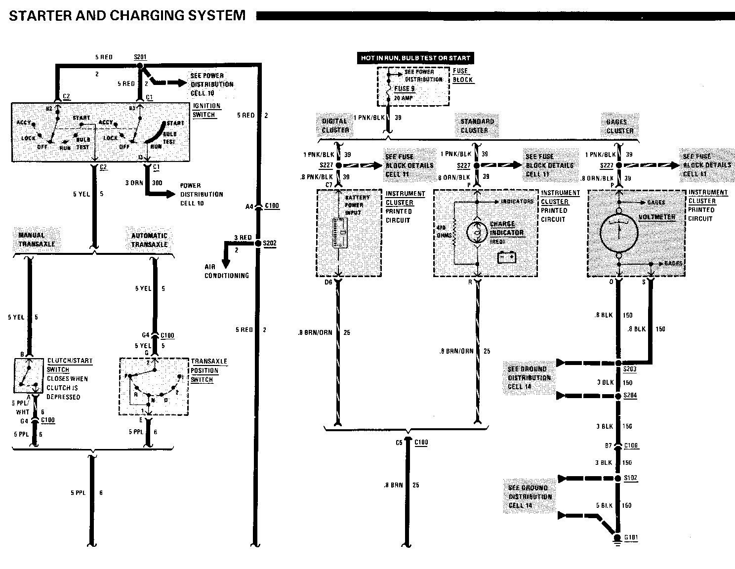
STARTER & CHARGING SYSTEM DIAGNOSIS- MANUAL UPDATE

VEHICLES AFFECTED: 1988 L CAR
The following pages (8A-30-0 and 8A-30-5) should replace the current pages in the 1988 L car Service Manual.
STARTER AND CHARGING SYSTEM
(Continued from previous page) A: CHARGE INDICATOR (IF EQUIPPED) DOES NOT LIGHT WITH IGNITION SWITCH IN RUN AND ENGINE STOPPED
Connect: FUSED JUMPER
At: GENERATOR CONNECTOR
(Disconnected)
Condition:
Ignition Switch: RUN
Connect Correct Result For Diagnosis Between -------------- ------------- ------- L (BRN) & Charge Ground Indicator See 1 lights
If the result is correct, repair/replace the Generator. Refer to Section 6D.
1. Check BRN and BRN/ORN (25) wires, PNK/BLK and ORN/BLK (39) wires, Indicator bulb, resistor and Instrument Cluster Printed Circuit for opens (see schematic).
B: CHARGE INDICATOR (IF EQUIPPED) STAYS ON WHEN THE ENGINE IS RUNNING
Disconnect: CONNECTOR
At: GENERATOR
Condition:
Ignition Switch: RUN
Disconnect Correct Result For Diagnosis ---------- -------------- ------------- Volts Generator Indicatordoes See 1 Connector not light
If the result is correct, repair/replace the Generator. Refer to Section 6D.
1. Check/repair BRN and BRN/ORN (25) wires and the Instrument Cluster Printed Circuit for shorts to ground (see schematic).
C: BATTERY IS UNDERCHARGED OR OVERCHARGED (TABLE 1)
Measure: VOLTAGE
At: GENERATOR BATTERY TERMINAL and GENERATOR CONNECTOR
(Disconnected)
Condition:
Ignition Switch: RUN
Measure Correct For Diagnosis Between Voltage ------- ------- -------------- L (BRN) & Ground
(Standard and Battery See 1 Digital Clusters only)
S (BLK/RED) Battery See 2 & Ground
Battery Terminal & Battery See 3 Ground
F (TAN/WHT) Battery See 4 &Ground
If all voltages are correct, reconnect the connector and go to Table 2.
1. Check/repair BRN and BRN/ORN (25) wires, PNK/BLK and ORN/BLK (39) wires, Indicator bulb, resistor and Instrument Cluster Printed Circuit for opens. (see schematic).
2. Check/repair BLK/RED (2) wire and Fusible Link B for an open (see schematic).
3. Check/repair BLK/RED (2) wire and Fusible Link C (see schematic).
4. Check/repair TAN/WHT and BRN (250) wires and Fuse 4 for an open (see schematic).
C: BATTERY IS UNDERCHARGED OR OVERCHARGED (TABLE 2)
Measure: VOLTAGE
At: GENERATOR BATTERY TERMINAL
Conditions:
Generator Connector: CONNECTED All accessories: OFF Engine running at fast idle
Measure Correct For Diagnosis Between Voltage ------- -------- -------------- Battery Less than 16 Terminal & volts See 1 Ground
If the voltage is correct, perform a Generator Load Test. Refer to Section 6D. If Generator is good, perform a Battery Load Test. Refer to Section 6D.
1. Repair/replace Generator. Refer to Section 6D.

General Motors bulletins are intended for use by professional technicians, not a "do-it-yourselfer". They are written to inform those technicians of conditions that may occur on some vehicles, or to provide information that could assist in the proper service of a vehicle. Properly trained technicians have the equipment, tools, safety instructions and know-how to do a job properly and safely. If a condition is described, do not assume that the bulletin applies to your vehicle, or that your vehicle will have that condition. See a General Motors dealer servicing your brand of General Motors vehicle for information on whether your vehicle may benefit from the information.
