Tools Required
GE-47827 Socket
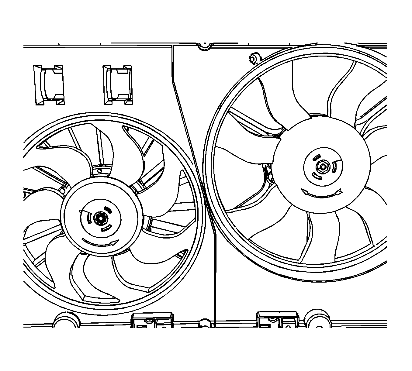
This vehicle is equipped with counter-rotating engine cooling fans. The right hand fan will require the use of GE-47827 or equivalent for fan blade removal. The left hand fan blade can be removed using a normal six point socket.
Removal Procedure
Caution: An electric fan under the hood can start up even when the engine is not running and can injure you. Keep hands, clothing and tools away from any underhood electric fan.
Caution: To help avoid personal injury or damage to the vehicle, a bent, cracked, or damaged fan blade or housing should always be replaced.
Caution: Unless directed otherwise, the ignition and start switch must be in the OFF or LOCK position, and all electrical loads must be OFF before servicing any electrical component. Disconnect the negative battery cable to prevent an electrical spark should a tool or equipment come in contact with an exposed electrical terminal. Failure to follow these precautions may result in personal injury and/or damage to the vehicle or its components.
- Remove the fan shroud assembly from the vehicle. Refer to Cooling Fan and Shroud Replacement .
- Using GE-47827 or equivalent , turn the fan motor drive plate in the opposite direction of the arrow stamped on the fan blade.
- Remove and discard the fan blade.
- Center punch each of the rivets (1) from the rear of the motor.
- Drill the head of the rivets (1) from the fan motor using a 6.35 mm (0.25 in) drill bit.
- Tap the rivets out of the fan shroud.
- Remove the fan motor from the fan shroud.
- Remove the tape covering the entry points from the fan motor.
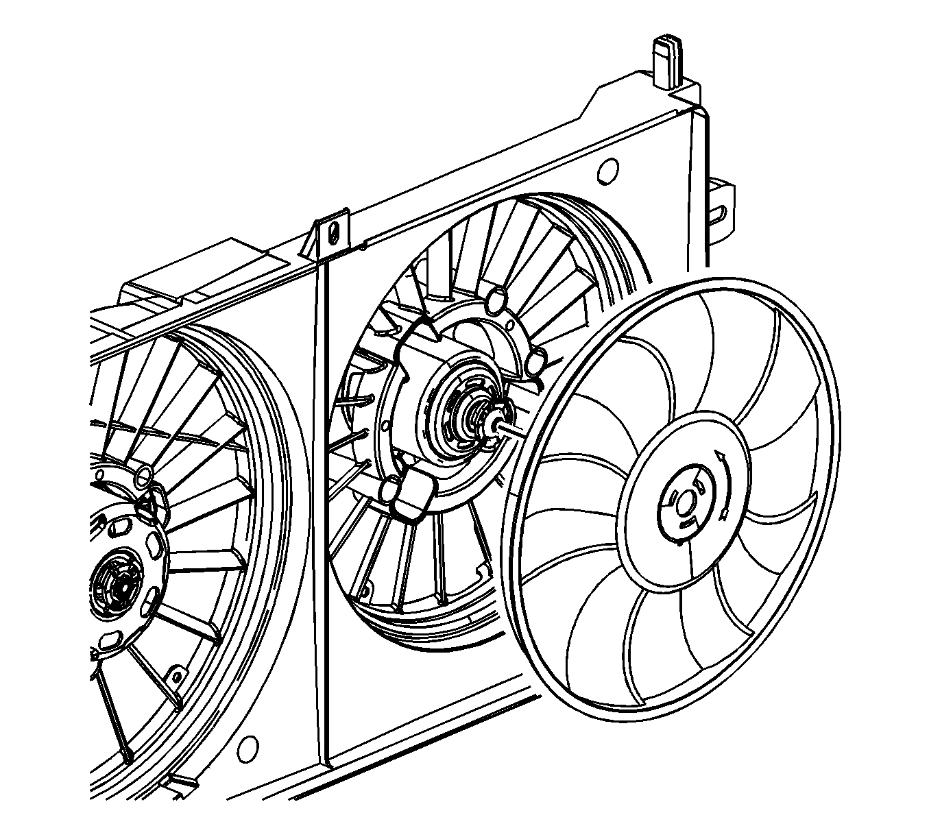
Important: Hold the fan blade to prevent rotation.
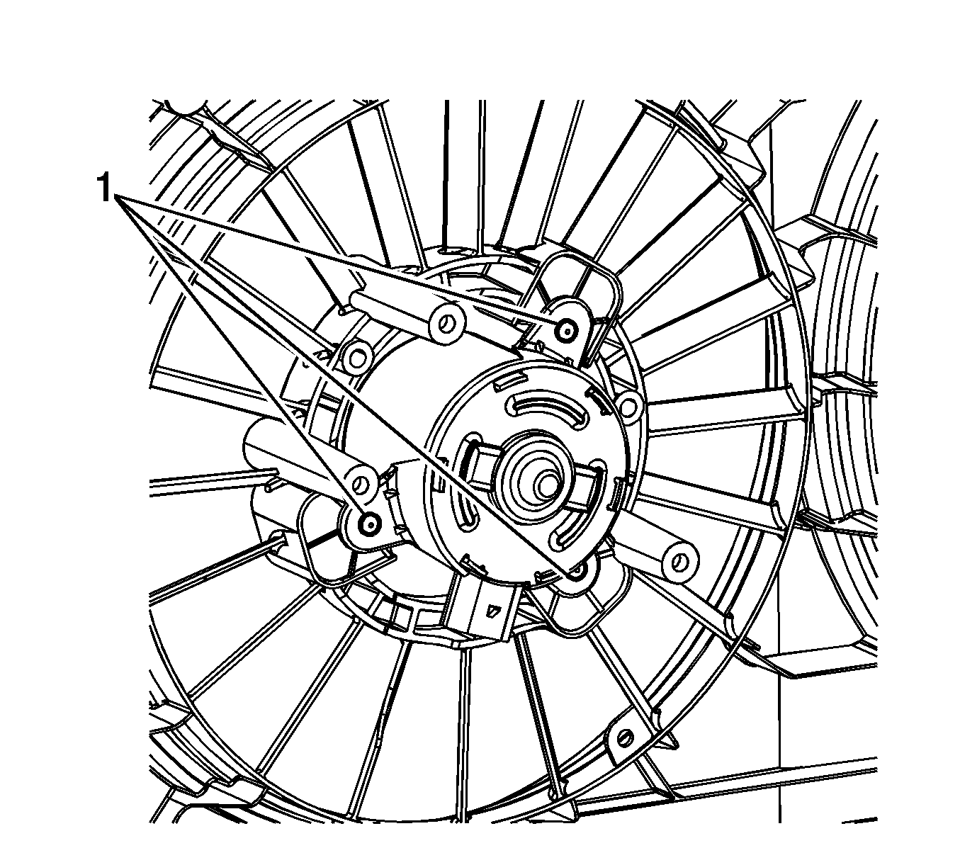
Notice: Prior to center punching and drilling out rivets, support the fan motor and shroud by placing a block of wood or other solid object under the fan motor. Failure to support the fan motor while drilling may result in a cracked fan shroud.
Notice: Failure to tape off all of the entry points to the cooling fan motor(s) will allow debris to enter and damage the motor(s).
Important: When reusing the fan motor(s) tape off the front and rear entry points of the fan motor(s) before drilling the rivets. Support the fan motor(s) and shroud prior to center punching the rivets.
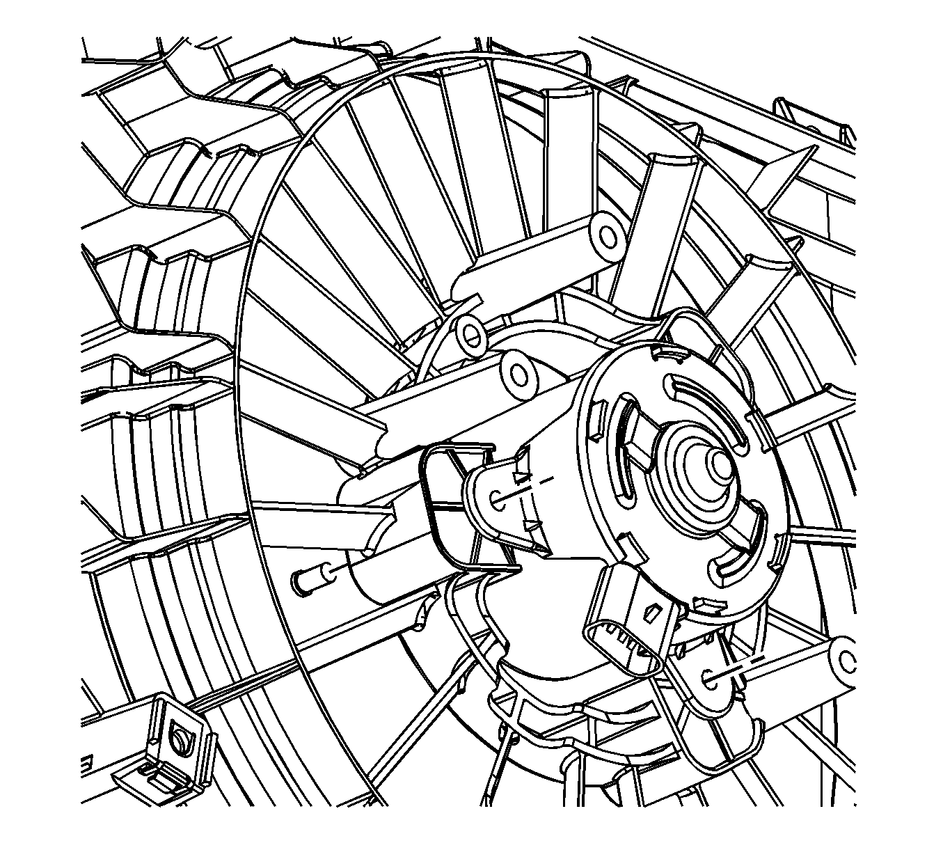
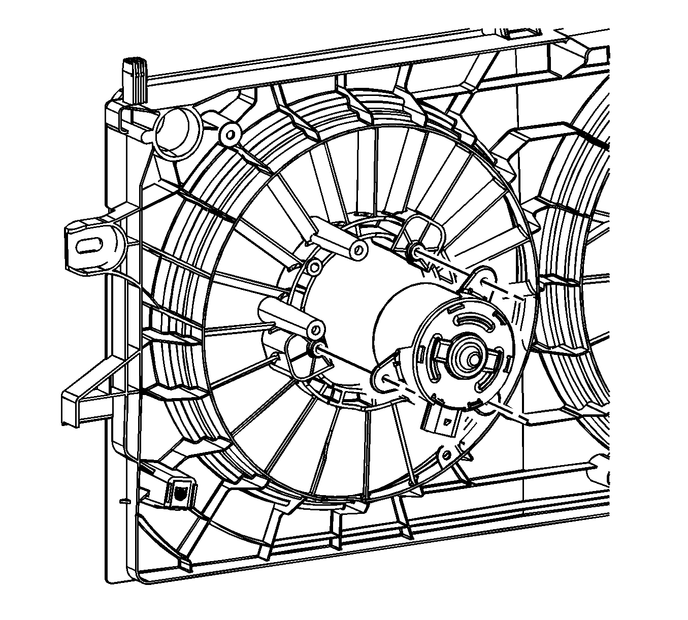
Important: Blow off any excess debris from the fan motor.
Installation Procedure
- Install the engine cooling fan motor to the fan shroud.
- Install the cooling fan motor bolts.
- Install the cooling fan motor nuts.
- Install the new engine cooling fan blade.
- Using the GE-47827 , or equivalent turn the fan motor drive plate in the same direction of the arrow on the fan blade until the fan motor drive plate engages to the fan blade.
- Rotate the cooling fan blade to ensure proper rotation.
- Install the fan shroud assembly to the vehicle. Refer to Cooling Fan and Shroud Replacement .

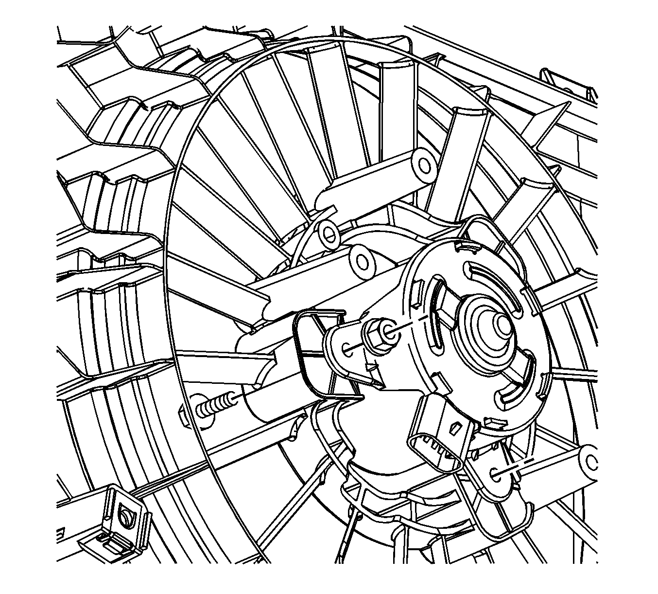
Important: Position the fan motor to the fan shroud and insert the bolts from the front side.
Notice: Refer to Fastener Notice in the Preface section.
Tighten
Tighten the nuts to 6 N·m (53 lb in).

Notice: Failure to heat the fan hub in hot tap water before installation will result in cooling fan failure due to cracking. Allowing the heated fan to cool for more than one minute prior to installation will also result in failure due to cracking.
Important: Using hot tap water at a minimum of 49°C (120°F), hold the new fan blade hub under the running water for a minimum of 60 seconds to heat the fan blade to the temperature of the water.
Immediately after heating, position the fan blade on the fan motor drive plate.