For 1990-2009 cars only
Removal Procedure
- Raise and support the vehicle. Refer to Lifting and Jacking the Vehicle.
- Remove the tire and wheel assembly. Refer to Tire and Wheel Removal and Installation.
- Remove the lower control arm assembly. Refer to Rear Axle Lower Control Arm Replacement.
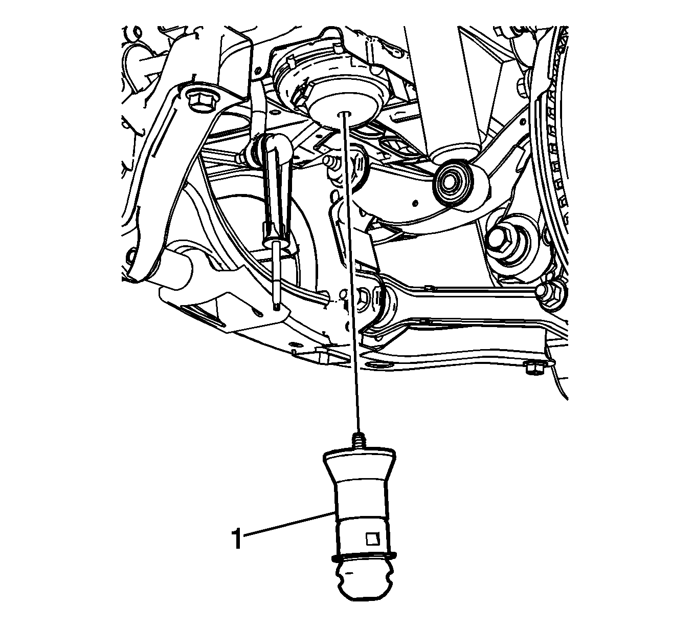
- Remove the rear suspension jounce bumper (1).
Installation Procedure
- Install the rear suspension jounce bumper (1) and tighten until the jounce bumper just makes contact with the mounting bracket.
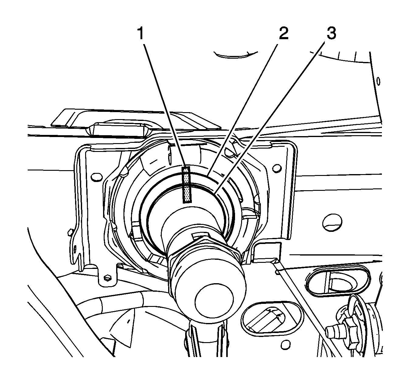
- Using a grease pencil or equivalent, create a reference mark (1) from the jounce bumper (3) to the mounting bracket (2).
- Tighten the jounce bumper (3) by rotating it 360° or one full turn.
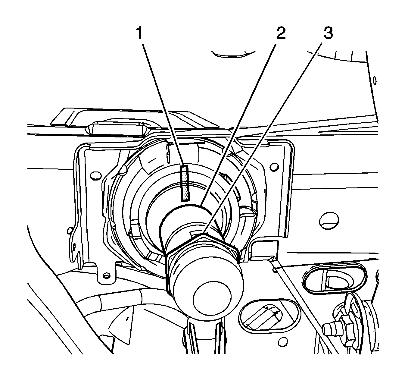
- Using the reference mark (1) as a starting point, rotate the jounce bumper (2) an additional 120° or two points of the hex nut (3) on the jounce bumper.
- Install the lower control arm assembly. Refer to Rear Axle Lower Control Arm Replacement.
- Install the tire and wheel assembly. Refer to Tire and Wheel Removal and Installation.
- Remove the support and lower the vehicle.