Special Tools
| • | J-21867-50 Transmission Line Pressure Adapter |
| • | J 21867 Pressure Gage |
- Raise and support the vehicle. Refer to Lifting and Jacking the Vehicle.
- Remove the left front splash shield. Refer to Engine Splash Shield Replacement.
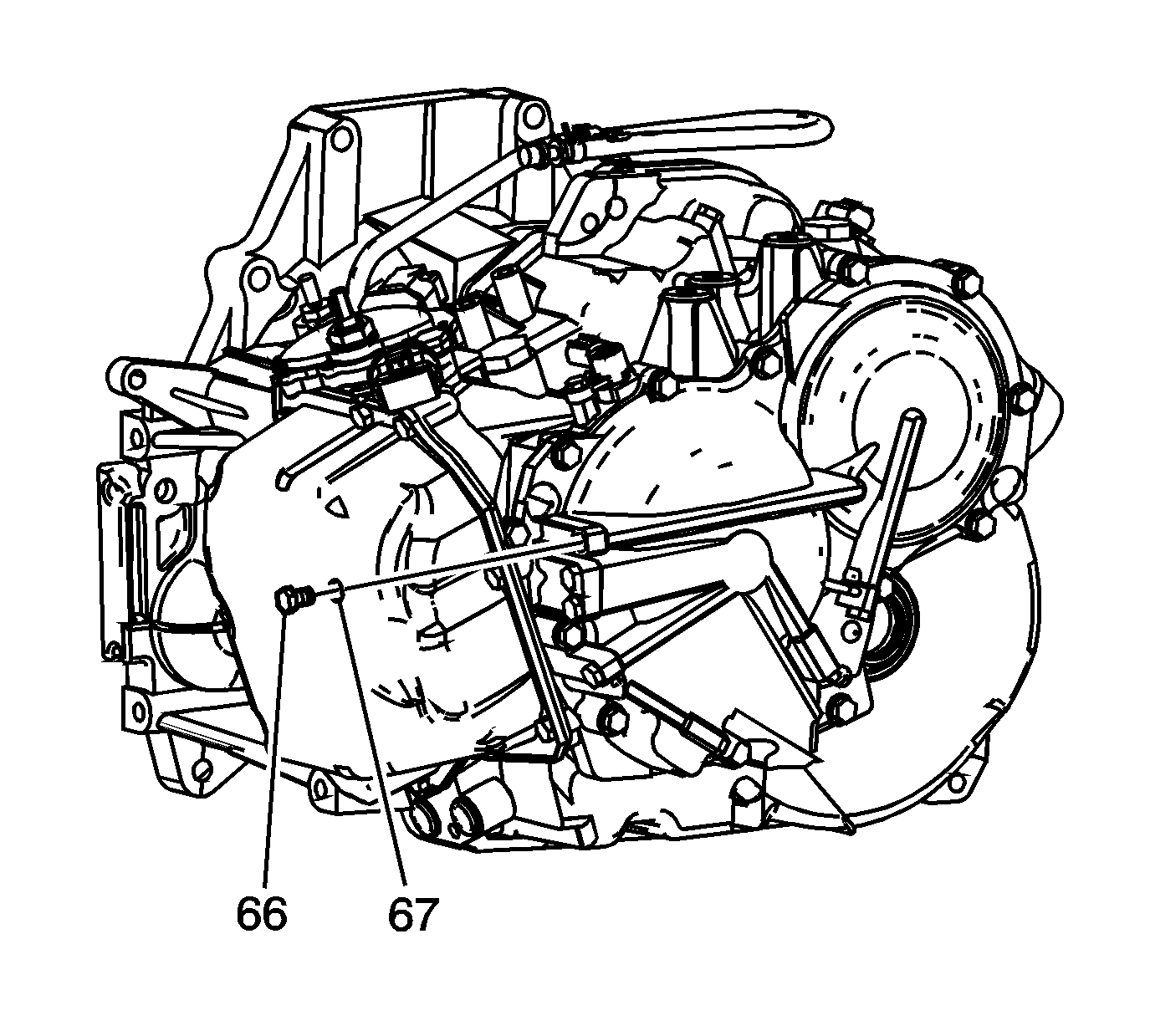
- Remove the automatic transmission fluid pressure test hole plug (66) and O-ring seal (67).
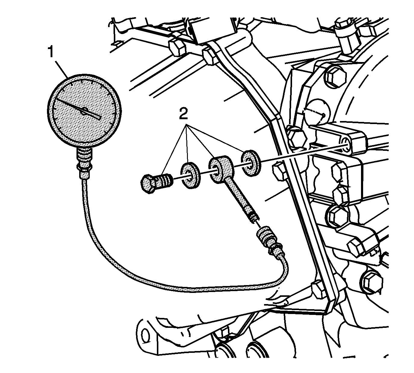
- Install the J-21867-50 (2) with a sealing washer on each side of the adapter into the test hole.
- Install the quick connect fitting of the J-21867-50 on the hose of J 21867 .
- Connect the J 21867 (1) to the J-21867-50 (2).
- Fully apply the parking brake.
- Connect a scan tool for engine RPMs.
- Start the engine and allow the engine to warm up at idle.
- Firmly apply the brake and shift into REVERSE (R).
- Allow the engine to idle and record the line pressure: 500-610 kPa (73-89 psi).
- Increase the engine speed to 2900 RPM and record the line pressure: 1710-1980 kPa (248-287 psi).
- Allow the transmission fluid to cool at idle in PARK (P) for at least one minute.
- Firmly apply the brake and shift into DRIVE (D).
- Allow the engine to idle and record the line pressure: 330-390 kPa (48-57 psi).
- Increase the engine speed to 2900 RPM and record the line pressure: 1280-1390 kPa (186-202 psi).
- If the line pressure reading is not within specifications refer to the Line Test Results table.
- Remove the tools and install the automatic transmission fluid pressure test hole plug (66) and a new O-ring (67). Tighten the test hole plug to 7 N·m (62 lb in).
- Install the left front splash shield. Refer to Engine Splash Shield Replacement.


Note: Do not perform the 2900 RPM test longer than 5 seconds.
Note: Do not perform the 2900 RPM test longer than 5 seconds.

Caution: Use the correct fastener in the correct location. Replacement fasteners must be the correct part number for that application. Fasteners requiring replacement or fasteners requiring the use of thread locking compound or sealant are identified in the service procedure. Do not use paints, lubricants, or corrosion inhibitors on fasteners or fastener joint surfaces unless specified. These coatings affect fastener torque and joint clamping force and may damage the fastener. Use the correct tightening sequence and specifications when installing fasteners in order to avoid damage to parts and systems.
Result | Possible Cause | ||||||||
|---|---|---|---|---|---|---|---|---|---|
HIGHER than specification in BOTH DRIVE AND REVERSE |
| ||||||||
LOWER than specification in BOTH DRIVE AND REVERSE |
| ||||||||
LOWER than specification in DRIVE ONLY |
| ||||||||
LOWER than specifications in REVERSE ONLY |
|
