For 1990-2009 cars only
Removal Procedure
Warning: Refer to Brake Fluid Irritant Warning in the Preface section.
Caution: Refer to Brake Fluid Effects on Paint and Electrical Components Caution in the Preface section.
- Remove the underhood electrical center bracket. Refer to Underhood Electrical Center or Junction Block Bracket Replacement.
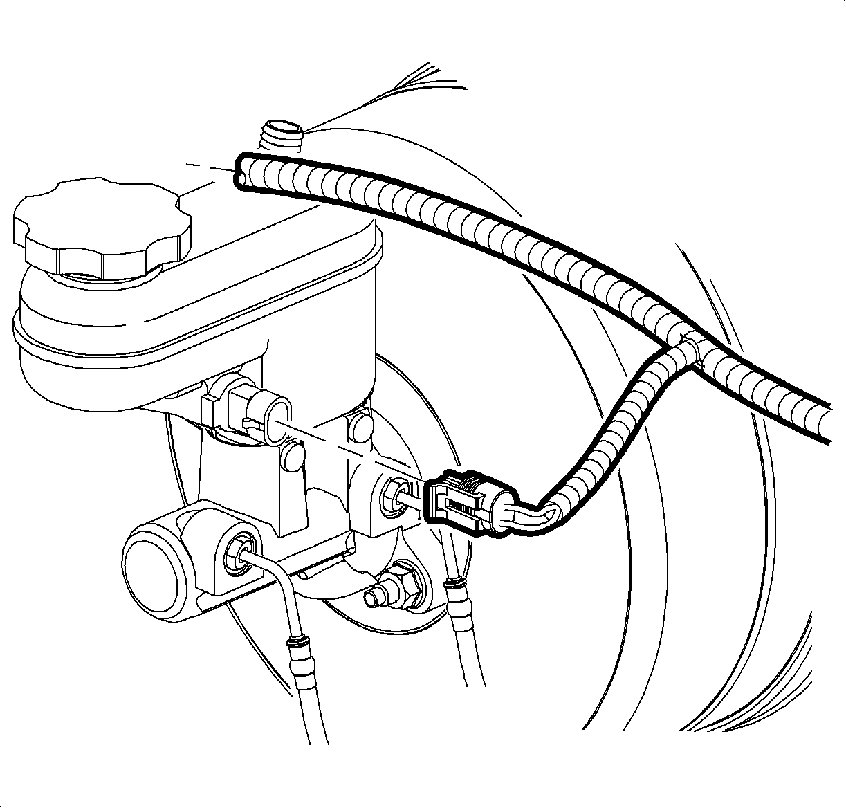
- Disconnect the electrical connector from the brake fluid level indicator switch.
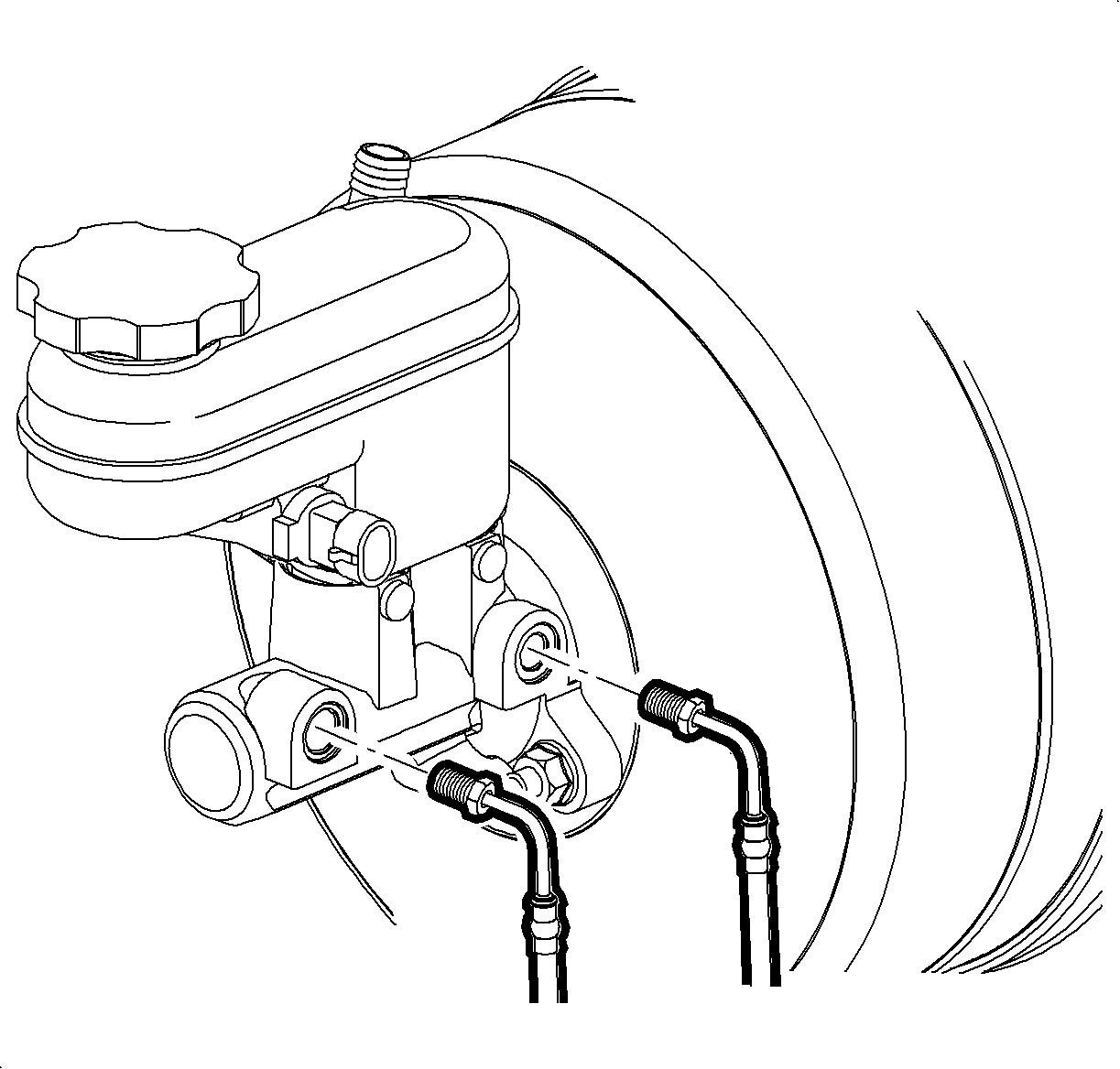
- Disconnect the brake pipes from the master cylinder.
- Plug the open brake pipe ends.
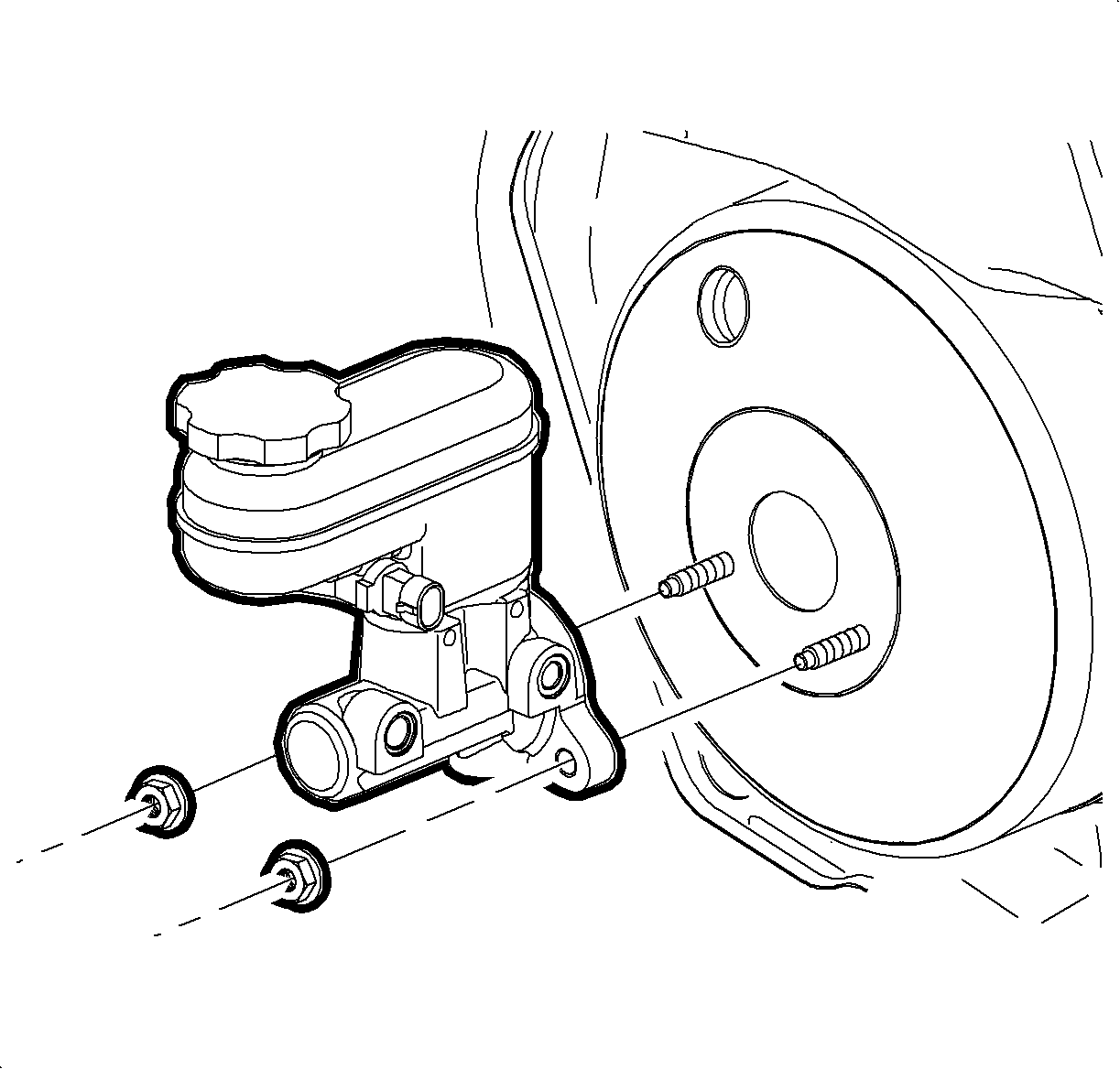
- Remove master cylinder mounting nuts.
- Remove the master cylinder from the vehicle.
- Drain the master cylinder reservoir of all brake fluid.


Note: Install a rubber cap or plug to the exposed brake pipe fitting ends in order to prevent brake fluid loss and contamination.

Installation Procedure
- Bench bleed the master cylinder. Refer to Master Cylinder Bench Bleeding.
- Install the master cylinder to the brake booster.
- Install the master cylinder mounting nuts and tighten to 25 N·m (18 lb ft).
- Remove the plugs from the brake pipes.
- Connect the brake pipes to the master cylinder.
- Connect the electrical connector to the brake fluid level indicator switch.
- Install the underhood electrical center bracket. Refer to Underhood Electrical Center or Junction Block Bracket Replacement.
- Bleed the hydraulic brake system. Refer to Hydraulic Brake System Bleeding.

Caution: Refer to Fastener Caution in the Preface section.

Tighten the brake pipe fittings at the master cylinder to 18 N·m (13 lb ft).

