BINDING/STICKING OR HARD TO OPEN FUEL FILTER DOOR

Subject: BINDING/STICKING OR HARD TO OPEN FUEL FILLER DOOR (NEW SPRING AND RELEASE CABLE) Models Affected: 1990-93 TRANS SPORT MODELS
CONDITION:
Fuel filler doors that:
1. Don't open when the release cable is pulled OR; 2. Have high efforts when operating the release cable.
CAUSE:
1. Door binds on hinge spring or cable is disconnected. 2. Cable may be routed improperly, causing binds.
CORRECTION:
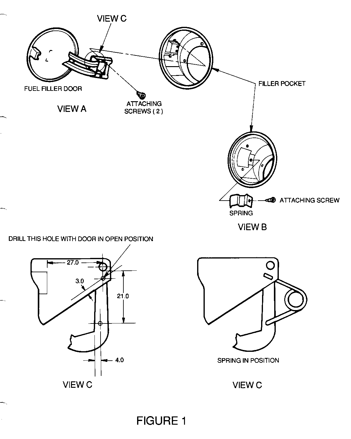
1. Modify the door by removing the original spring and installing a new hinge spring, see Figure 1.
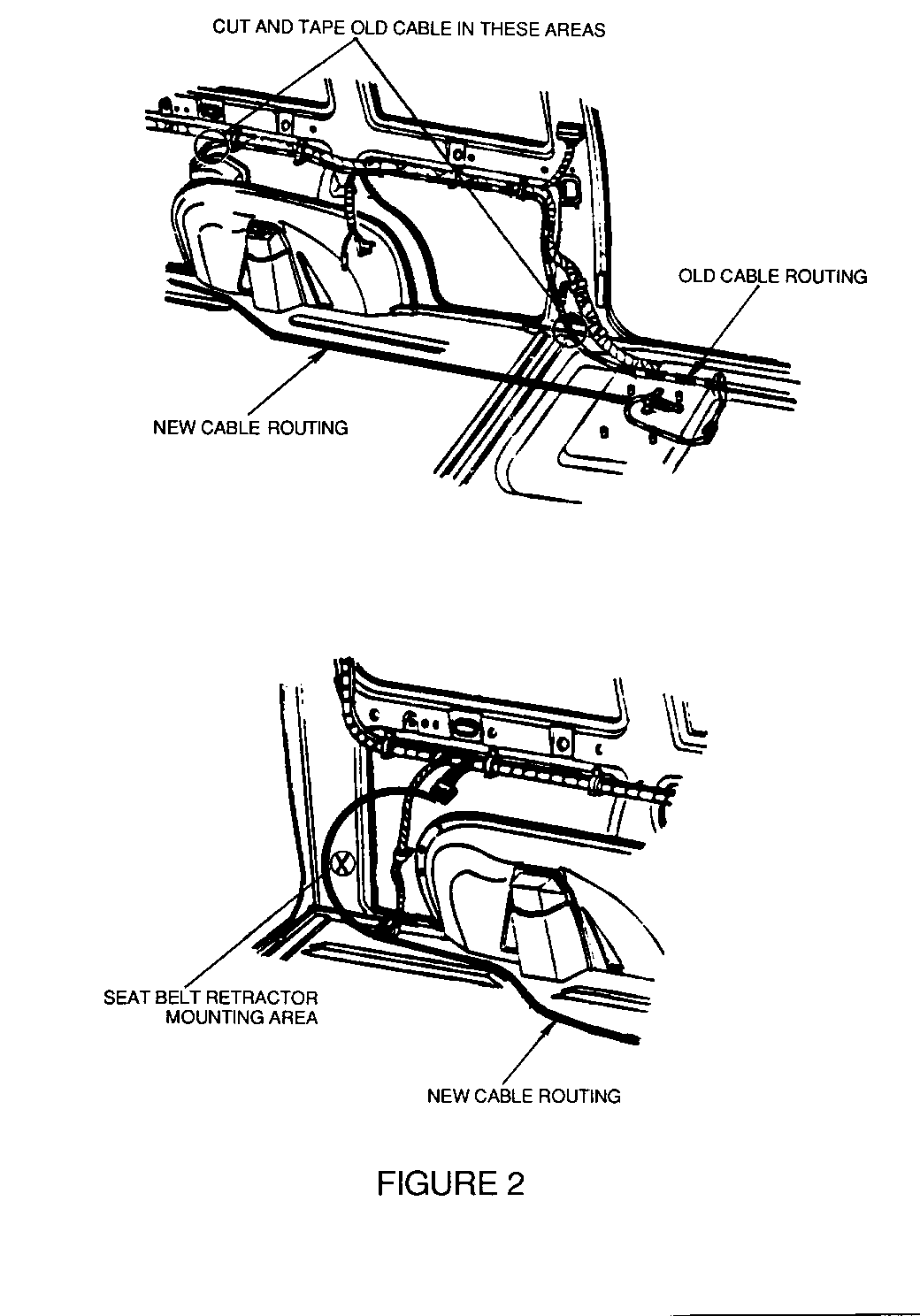
2. In some cases, it may be necessary to replace the release cable. In those cases, the cable can be cut at both ends (leaving the majority of the cable with the vehicle), and install a new cable per the routing shown in Figure 2.
DIAGNOSIS:
1. Open fuel filler door.
NOTE: If door is stuck closed, it can be opened by inserting a plastic card into the gap at the rear of the door opening and pushing the card inward to release the latch pawl.
- If the door was stuck closed, or did not "spring" open when the cable was released, replace the door spring.
2. With the door open, operate the cable and check for smooth operation with low efforts. With the aid of a helper, check that the latch pawl releases the door when operating the cable.
- If the cable did operate smoothly with low efforts, DO NOT remove or reposition the existing cable.
- If the cable was damaged, had high efforts OR, the latch pawl did not release when operating the release handle, replace the cable and use the new routing shown on Figure 2.
MATERIALS REQUIRED: P/N 10244175 SPRING, FUEL FILLER DOOR P/N 10228633 CABLE, FUEL FILLER DOOR RELEASE
PROCEDURE FOR NEW SPRING INSTALLATION:
1. Open fuel filler door and remove the two door attaching screws, see Figure 1, View A.
2. Remove door from opening.
3. Remove and discard the door hinge spring attaching screw and spring from the fuel filler pocket (Figure 1, View B).
4. Using Figure 1, View C, locate the holes to be drilled in the fuel filler door hinge.
-The hole on the hinge box is dimensioned 27.0 mm from the flat surface of the "boss" and 3.0 mm from the edge as indicated in View C. Drill this hole with the door in the open position.
-The hole on the hinge arm is dimensioned 21.0 mm from the edge of the pivot (inside the hinge box) and 4.0 mm from the inside edge of the hinge arm as indicated in View C.
5. Using an electric drill motor and 5/64" drill bit, drill the two holes for the new spring.
6. Install the new spring on the door hinge (Figure 1, View C).
7. Inspect the release cable to ensure proper operation.
8. Reinstall the door on the fuel filler pocket.
9. Operate the cable and door to ensure proper function.
PROCEDURE FOR INSTALLING CABLE TO NEW ROUTING:
The new routing for the cable should be as straight as possible from the front seat to the rear body pillar, and the return "loop" as wide as possible (see Figure 2).
1. Open sliding side door and rear lift gate.
2. Remove seats on second row (and third row if equipped).
3. Remove the seat anchor plate covers and plugs at all left side outboard locations.
4. Remove the left door sill plate and loosen the left side center pillar garnish molding by removing the attaching screw and upper seat belt anchor bolt.
5. Remove the left side ELC assembly (left side Jack Stowage) access door on the rear quarter trim panel.
6. Using a door trim pad tool (J 24595B), remove the left side ELC panel (left rear bumper fascia access cover) retaining pins and the panel.
7. Remove the left side quarter trim rear finish molding assembly.
8. Open the fuel filler door and remove the latch attaching screw and pull the latch from pocket.
9. Open the latch cover and disengage the cable from the latch.
10. Cut the original cable in the areas shown in Figure 2 and tape the remaining ends to the wiring harness to prevent rattles.
NOTE: It may be possible to pull the cable rearward and completely remove it, once the forward end has been cut.
11. Raise the driver seat to full up position and loosen the seat to floor attaching bolts.
12. Remove the forward end of the original cable from the release lever and discard.
13. Using a piece of welding rod or coat hanger as a tool, (fish wire) insert the rod through the slit in the carpet below the front seat and push rearward under the carpet until it exits at the second seat forward anchor plate access hole.
14. Tape or fasten the new cable (forward end) to the rod and pull the cable under the carpet and through the slit below the front seat.
15. Disconnect the cable from the rod and fasten the cable end to the latch. DO NOT fasten the cable casing to the latch at this time.
16. Insert the cable rearward through the seat anchor plate hole areas under the carpet, being careful to keep the sealing grommet near the rear end of the cable.
17. Using the same rod tool as a "fish wire", pull the cable under the carpet and behind the quarter trim at the ELC assembly compartment area.
18. Route the cable rearward of the seat belt retractor on the rear body pillar.
19. Route the cable forward through the hole in the wheelhouse, into the fuel filler pocket area and position the sealing grommet in the hole.
20. Connect the cable to the latch and housing, snap the cover to retain the cable and reinstall the latch to the fuel filler pocket (Torque screw to 7 N.m (62 lbs in.).
21. Position the forward end of the cable casing to the release lever and install at one of the 3 locations provided for cable adjustment.
22. Close the fuel filler door and operate the system several times to ensure proper operation.
23. Tape the cable to the rear body lock pillar surface using cloth body tape or duct tape to prevent rattles.
24. Reinstall all previously removed trim items, making sure that the cable is positioned away from any potential pinch points (at seat anchor plate covers, quarter trim, seat belt retractor, driver's seat attachments, etc.).
- Torque upper seat belt anchor bolt 42 N.m (31 lbs. ft.). - Torque driver's seat attachments 27 N.m (20 lbs. ft.).
PART AVAILABILITY:
Parts are currently available from GMSPO.
WARRANTY INFORMATION:
Labor Operation: New Time Allowance: - Door Spring: T3328 0.4 Hrs. - Release Cable: R4085 Use Applicable Time


General Motors bulletins are intended for use by professional technicians, not a "do-it-yourselfer". They are written to inform those technicians of conditions that may occur on some vehicles, or to provide information that could assist in the proper service of a vehicle. Properly trained technicians have the equipment, tools, safety instructions and know-how to do a job properly and safely. If a condition is described, do not assume that the bulletin applies to your vehicle, or that your vehicle will have that condition. See a General Motors dealer servicing your brand of General Motors vehicle for information on whether your vehicle may benefit from the information.
