SERVICE MANUAL UPDATE SEC. 6E2 (HARDWARE CHANGES)

Subject: SERVICE MANUAL UPDATE - SECTION 6E2 REVISED PAGES
Models Affected: 1992 TRANS SPORT MODELS WITH 3.1L (VIN D) RPO LG6
The following pages are revisions to the 1992 Trans Sport Service Manual and reflect current changes to these vehicles.
Current revisions include the following pages.
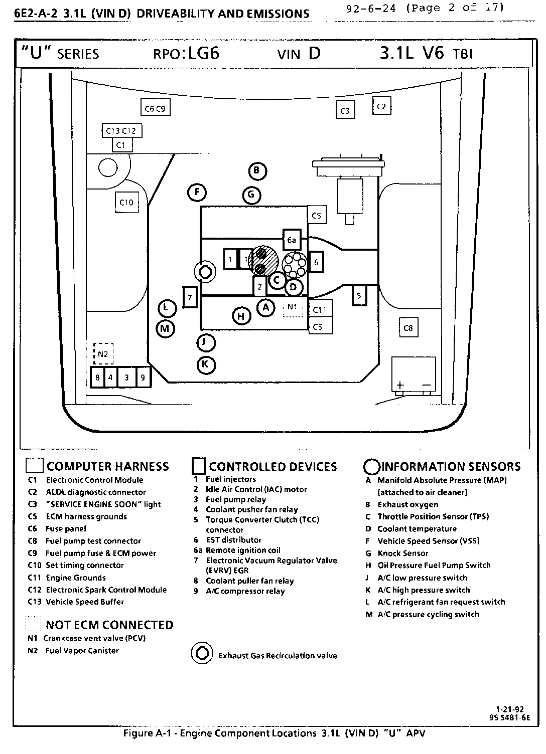
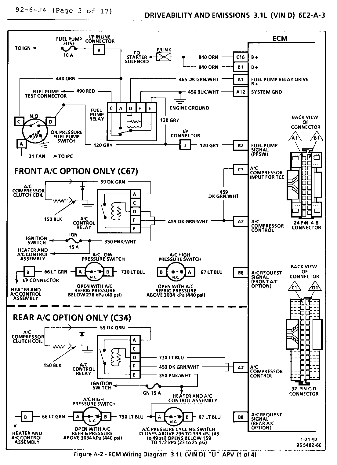
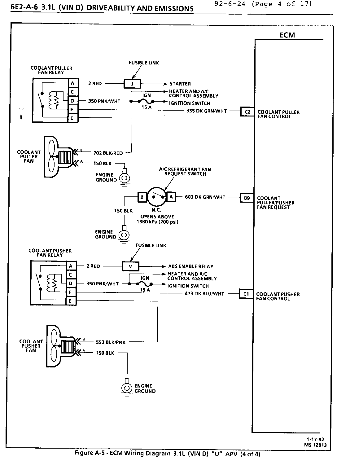
6E2-A2 Component Location - Figure A-1. 6E2-A3 ECM Wiring Diagram - Figure A-2 (Page 1 of 4). 6E2-A6 ECM Wiring Diagram - Figure A-5 (Page 4 of 4).
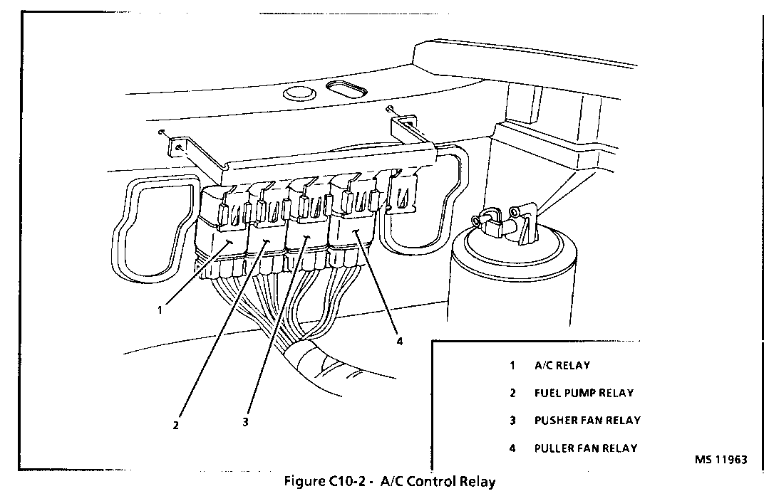
Section 6E2-C10 ECM Controlled Air Conditioning "Operations". Section 6E2-C10 A/C Control Relay Center - Figure C10-2. Section 6E2-C10 Diagnostic Chart C10 (Page 1 of 2) and Facing Page. Section 6E2-C10 Diagnostic Chart C10 (Page 2 of 2) and Facing Page.
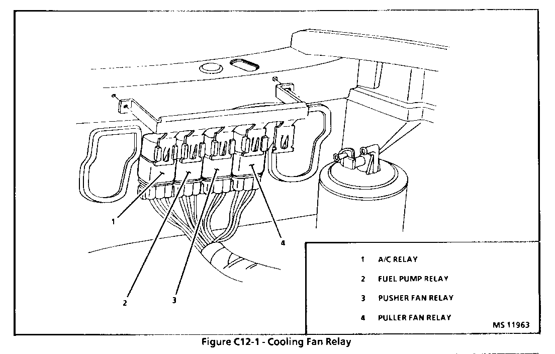
Section 6E2-C12 Coolant Fan Control "Operations". Section 6E2-C12 Coolant Fan Relay Locations. Section 6E2-C12 Diagnostic Chart C12 (Page 1 of 2) and Facing Page. Section 6E2-C12 Diagnostic Chart C12 (Page 2 of 2) and Facing Page.
This bulletin indicates current hardware changes due to the availability of a rear A/C option package for all 1992 Trans Sport vehicles.
SECTION C10 ECM CONTROLLED AIR CONDITIONING
CONTENTS
General Description . . . . . . . . . . . . . . . . . .C10-1 Operation . . . . . . . . . . . . . . . . . . . . . . .C10-1 Diagnosis . . . . . . . . . . . . . . . . . . . . . . .C10-2 On-Vehicle Service . . . . . . . . . . . . . . . . . .C10-2
GENERAL DESCRIPTION
In order to improve idle quality and wide open throttle performance, the A/C compressor is controlled by the ECM.
The V-5 type of system (front A/C only C67) uses a compressor with a variable displacement. The V-5 type meets A/C requirements without cycling. HE-6 system uses a compressor that cycles (rear A/C only C34). For a description and an explanation of the components used, refer to SECTION 1B of the service manual.
OPERATION:
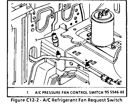
---------- This system consists of a heater and A/C control assembly located at dash board. A low pressure switch (front A/C option), a high pressure cut-out switch, A/C pressure cycling switch (rear A/C option). When A/C is requested ECM turns "ON" A/C relay(s) and the compressor. An A/C refrigerant activated fan request switch is also used to tell the ECM to turn "ON" the cooling fan(s) via cooling fan relay(s), when A/C head pressure is high. This switch opens when A/C pressure exceeds about 200 psi (1380 kPa).
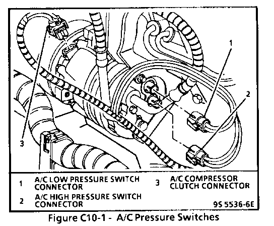
The low pressure switch, (front A/C option only) mounted in the compressor, is closed when the system contains a sufficient refrigerant charge and warm climate temperature exist. This switch opens, when pressure is less than about 40 psi (276 kPa).
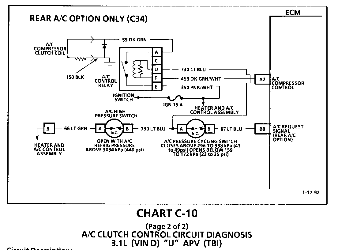
Vehicles equipped with rear A/C option utilize a pressure cycling switch on the accumulator. The pressure cycling switch is an evaporator freeze protection device and senses refrigerant pressure on the suction side of the system. This switch is located on a standard schrader type valve low side fitting. During air temperatures of 16-26 C (60-80 F), the equalized pressures within the charged A/C system will close the contacts of the pressure switch. As the compressor reduces the evaporator pressure to approximately 175 kPa (25 psi), the pressure switch will open, de-energizing the compressor clutch via the ECM. As the system equalizes and the pressure reaches approximately 315 kPa (45 psi), the pressure switch contacts close, re-energizing the clutch coil. This cycling continues and maintains evaporator discharge air temperature at approximately 1 C (33 F). Because of this cycling, some slight increases and decreases of engine speed/power may be noticed under certain conditions. This is normal as the system is designed to cycle to maintain desired cooling, thus preventing evaporator freeze-up.
The high pressure cut-out switch (normally closed) opens when head pressure gets too high. This disables the A/C clutch before damage can occur to the system. This switch opens, when pressure is greater than about 440 psi (3034 kPa).
The A/C control relay is controlled by the ECM, so that the ECM can increase idle speed before turning on the clutch, or disable the clutch during WOT, or temperatures above 123 C (243 F). A/C compressor clutch is inhibited from coming on until rpm is below 4000 rpm for 3 seconds.
Vehicles equipped with the front A/C option will allow TCC engagement at 2 different speeds. If A/C is selected "ON" the TCC will engage at approximately 35 mph, When A/C is selected "OFF," the TCC will engage at approximately 25 mph. This difference is due to the use of the V-5 non-cycling compressor used in front A/C equipped vehicles. The A/C control relay driver is connected to the TCC selector at the ECM allowing for a smooth engagement of the TCC when an A/C load is present.
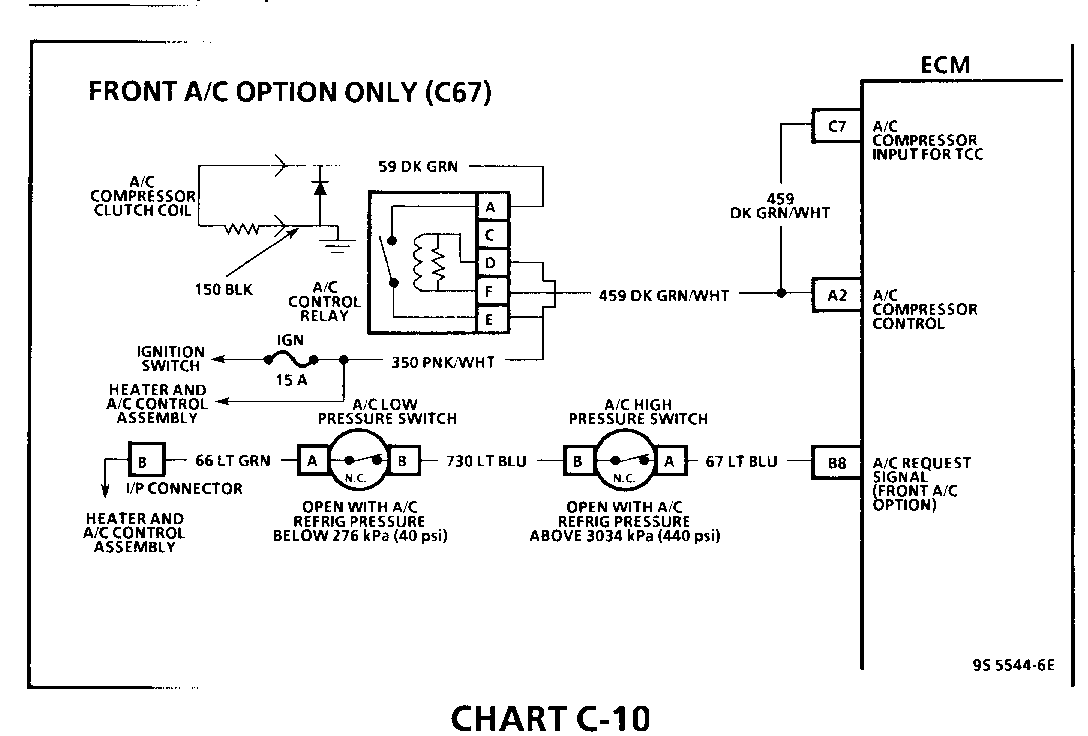
See appropriate C-10 chart for specific wiring and circuit description.
DIAGNOSIS
CHARTS C-10 should be used for diagnosing the electrical portion of the A/C circuit. SECTION 1B should be used for diagnosing the refrigerant portion of the system.
The Tech 1 "Scan" tool will be used in diagnosing the system, as it has the ability to read when the ECM has commanded the A/C clutch "ON."
ON-VEHICLE SERVICE
For removal and replacement procedures of A/C components, refer to SECTION 1B of the service manual.
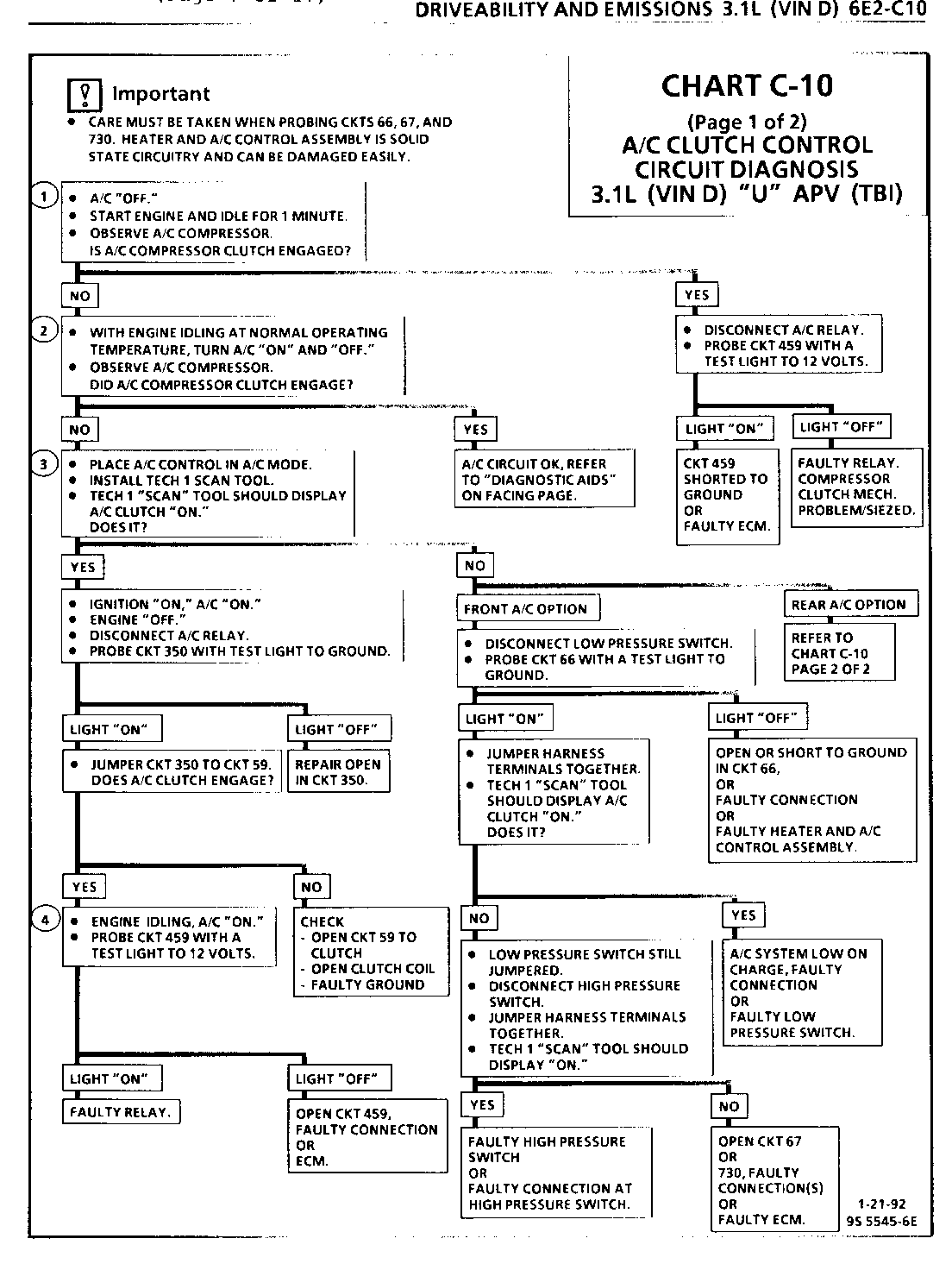
CHART C-10 (Page 1 of 2) A/C CLUTCH CONTROL CIRCUIT DIAGNOSIS 3.1 L (VIN D) "U" APV (TBI)
Circuit Description:
The A/C clutch control relay is ECM controlled to delay A/C clutch engagement about 8 seconds after engine is turned "ON." This allows the IAC to adjust engine rpm, before the A/C clutch engages. The ECM, also, causes the relay to disengage the A/C clutch during Wide Open Throttle (WOT), or if engine is overheating. The A/C clutch control relay is energized, when the ECM provides a ground path for CKT 459. The low pressure switch will open if A/C pressure is less than 40 psi (276 kPa). The high pressure switch will open, if A/C pressure exceeds about 440 psi (3034 kPa). Vehicles equipped with rear A/C option utilize a pressure cycling switch instead of a low pressure switch. A/C pressure cycling switch closes above 296 to 338 kPa (43 to 49 psi) opens below 159 to 172 kPa (23 to 25 psi). An A/C refrigerant fan request switch opens to request the fan(s) "ON," when A/C pressure exceeds about 200 psi (1380 kPa).
Test Description: Number(s) below refer to circled number(s) on the diagnostic chart.
1. The ECM will only energize the A/C relay, when the engine is running. This test will determine if the relay or CKT 459 is faulty.
2. Compressor clutch should apply if the following conditions have been met: Front A/C option only (C67). The low pressure switch must be closed and the high pressure switch must be closed, so the A/C request (12 volts) will be present at the ECM. Rear A/C option only (C34), A/C mode is requested via the high pressure and pressure cycling switches, 12 volts is supplied to the Relay coil via the high pressure switch. As the compressor reduces the evaporator pressure to approximately 175 kPa (25 psi), the pressure cycling switch will open, compressor clutch will cycle "OFF." As the system equalizes and the pressure reaches approximately 315 kPa (45 psi) the pressure cycling switch will close, compressor clutch will cycle "ON." This cycling continues and maintains evaporator discharge and temperature at approximately 1 C (33 F).
3. Determines if the signal is reaching the ECM on CKT 66 from the A/C control panel. Signal should only be present when the A/C mode or defrost mode has been selected.
4. With the engine idling and A/C "ON," the ECM should be grounding CKT 459, which should cause the test light to be "ON.
Diagnostic Aids:
If complaint was insufficient cooling, the problem may be caused by a inoperative cooling fan(s), or A/C refrigerant fan request switch. The engine cooling fan(s) should turn "ON," when A/C pressure exceeds a value to open the switch, which causes the ECM to energize the cooling fan relay(s). See CHART C-12, for cooling fan diagnosis. If fan operates correctly, see SECTION 1B.
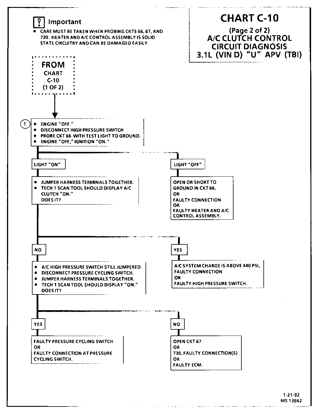
CHART C-10 (Page 2 of 2) A/C CLUTCH CONTROL CIRCUIT DIAGNOSIS 3.1L (VIN D) "U" APV (TBI)
Circuit Description:
The A/C clutch control relay is ECM controlled to delay A/C clutch engagement about 8 seconds after engine is turned "ON." This allows the IAC to adjust engine rpm, before the A/C clutch engages. The ECM, also, causes the relay to disengage the A/C clutch during Wide Open Throttle (WOT), or if engine is overheating. The A/C clutch control relay is energized, when the ECM provides a ground path for CKT 459. The high pressure switch will open, if A/C pressure exceeds about 440 psi (3034 kPa). Vehicles equipped with rear A/C option utilize a pressure cycling switch instead of a low pressure switch. A/C pressure cycling switch closes above 296 to 338 kPa (43 to 49 psi) opens below 159 to 172 kPa (23 to 25 psi).
Test Description: Number(s) below refer to circled number(s) on the diagnostic chart.
1. Determines if the signal is reaching the ECM from the A/C control panel. Signal should only be present when the A/C mode or defrost mode has been selected.
Diagnostic Aids:
If complaint was insufficient cooling, the problem may be caused by a inoperative cooling fan(s), or A/C refrigerant fan request switch. The engine cooling fan(s) should turn "ON," when A/C pressure exceeds 200 psi (380 kPa) to open the switch, which causes the ECM to energize the cooling fan relay(s). See CHART C-12, for cooling fan diagnosis. If fan operates correctly, see SECTION 1B.
SECTION C12 COOLING FAN CONTROL
CONTENTS
General Description . . . . . . . . . . . . . . . . . . .C12-1 Operation . . . . . . . . . . . . . . . . . . . . . . . .C12-1 Diagnosis . . . . . . . . . . . . . . . . . . . . . . . .C12-1 On-Vehicle Service . . . . . . . . . . . . . . . . . . .C12-1 Part information . . . . . . . . . . . . . . . . . . . .C12-1
GENERAL DESCRIPTION
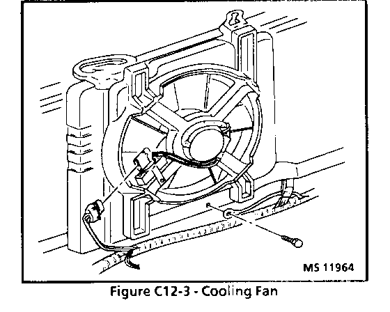
All front wheel drive vehicles with transversely mounted engines, and some other vehicles, use an electric cooling fan(s). The fan(s) is used for engine and A/C condenser cooling but the fan(s) only operates under certain conditions.
OPERATION
The electric cooling fan(s), on this engine, is totally controlled by the ECM. The ECM will ground the cooling fan relay(s), which turns "ON" the fan(s) when the following conditions are met:
- Puller fan; when engine temperature is above 106 C (223 F).
- Pusher fan; when engine temperature is above 11O C (230 F).
- A/C head pressure greater than 1380 kPa (200 psi) turns "ON" both cooling fans.
- Cooling fan(s) turn "OFF" below 100 C (217 F).
- Vehicle speed less than 8 Km/H (5 mph) fan(s) will remain "ON" with A/C request and remain "ON" for 45 seconds after A/C request turned "OFF."
The electric cooling fan operates when engine coolant temperature exceeds a certain value. The ECM completes the ground paths for the windings of the cooling fan relays located in the engine compartment. The relay contacts then close and complete the circuit between the 40 amp fusible link and the fan motor. When the fan is no longer required, the ECM removes the ground for the fan relays and the fan stops.
Whenever there is a fan "ON" request the fan will be running.
The ECM will complete the ground path for the winding of the low speed fan (Puller Fan) relay when it sees engine temperature above 106 C (210 F) or when A/C is requested. The fan will continue to run for approximately 45 seconds after the A/C request signal is gone. There is a six second delay for (Pusher Fan) to turn "ON" when (Puller Fan) is "ON. "Pusher Fan is also turned "ON" when engine coolant temperature is above 110 C (217 F). Both fans turn "OFF" below 100 C (217 F) and vehicle speed is above 5 mph.
The A/C head pressure switch signals the ECM to turn "ON" the fan relay(s) when A/C pressure exceeds 200 psi (1380 kPa). The fan will run at a higher speed when high speed fans (Pusher Fan) is called for.
DIAGNOSIS
The following C-12 circuit charts will diagnose the ECM controlled cooling fan for specific system description, components and wiring. Refer to "Coolant Fans" in SECTION 8A or the applicable C-12 Charts.
ON-VEHICLE SERVICE
Cooling system component replacement can be found in SECTION 6B.
PARTS INFORMATION
PART NAME GROUP --------- ----- Fan, Engine . . . . . . . . . . . . . . . . . . . . . . . 1.055 Motor, Fan . . . . . . . . . . . . . . . . . . . . . . . 1.055 Relay, Engine Fan . . . . . . . . . . . . . . . . . . . . 1.055 Switch, A/C Refrigerant Pressure . . . . . . . . . . . . 1.055
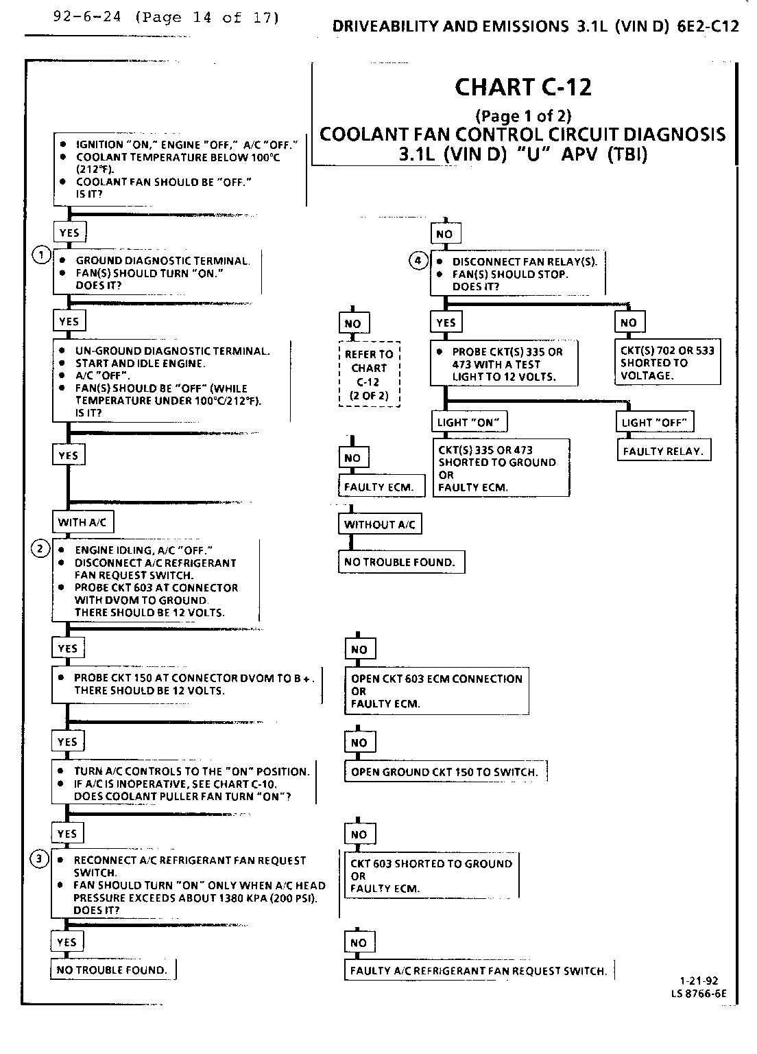
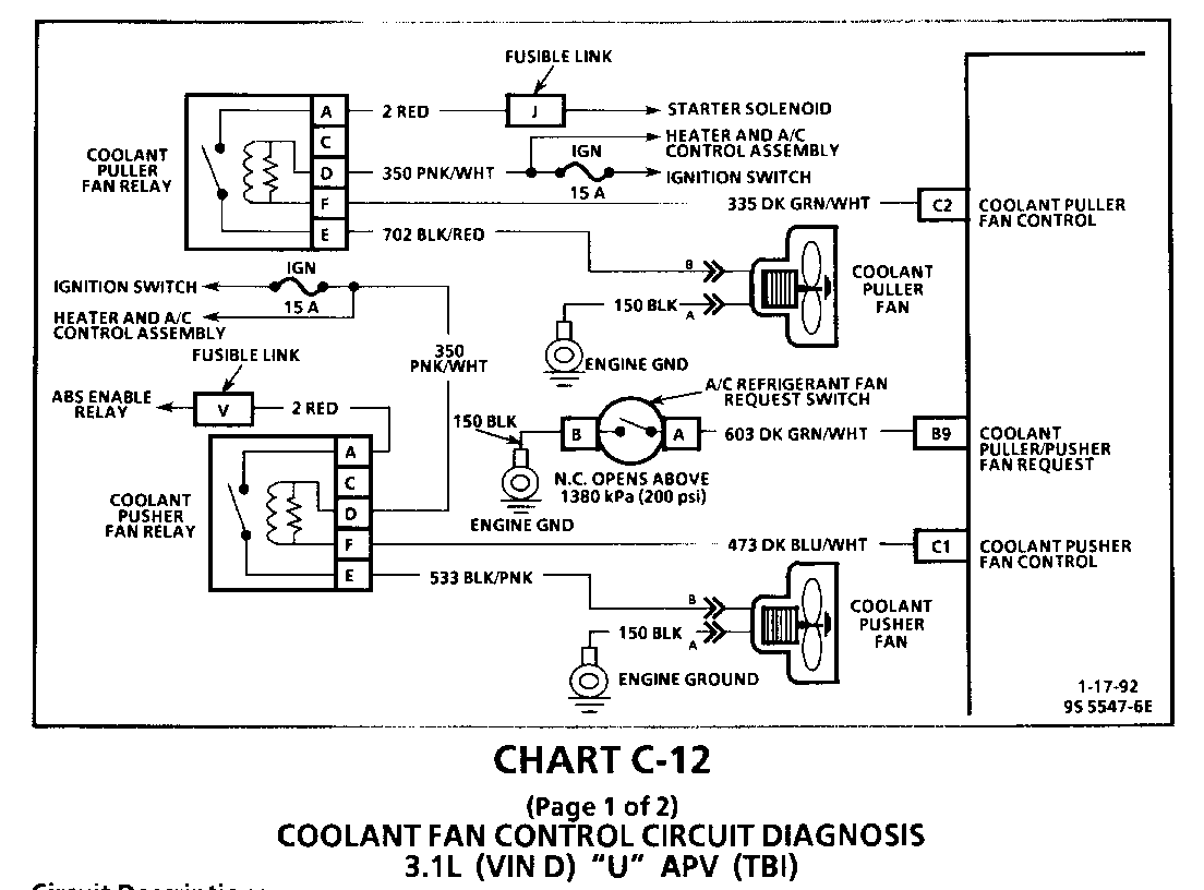
CHART C-12 (Page 1 of 2) COOLANT FAN CONTROL CIRCUIT DIAGNOSIS 3.1 L (VIN D) "U" APV (TBI)
Circuit Description:
The electric cooling fan is controlled by the ECM, based on inputs from the coolant temperature sensor, A/C request, A/C refrigerant fan request switch, and vehicle speed. The ECM controls the fan(s) by grounding CKT 335 and CKT 473, which energizes the fan control relay(s). Battery voltage is then supplied to the fan motor(s).
The ECM grounds CKT 335 (Puller Fan Relay), when coolant temperature is approximately 106 C (223 F), or when A/C has been requested, and the A/C refrigerant fan request switch opens with high A/C pressure, about 200 psi (1380 kPa).
The pusher fan relay is grounded by the ECM when coolant temperature is approximately 110 C (217 F) and/or puller fan is "ON" for A/C pressure.
Test Description: Number(s) below refer to circled number(s) on the diagnostic chart.
1. With the diagnostic terminal grounded, the cooling fan control driver(s) will close, which should energize the fan control relay(s).
2. If the A/C refrigerant fan request switch or circuit is open, the fan would run whenever A/C is requested.
3. With A/C requested and 45 sec after request removed, the A/C refrigerant fan request switch should open, when A/C high pressure exceeds about 1380 kPa (200 psi). This signal should cause the ECM to energize the fan control relay(s).
4. This test checks to see if the coolant puller and pusher fan relay(s) (CKTS 335 and 473) are shorted to ground. This condition would cause the fans to be "ON"constantly.
Diagnostic Aids:
If the owner complained of engine overheating problem, it must be determined if the complaint was due to an actual boil over, or the hot light, or temperature gage indicated over heating.
If the gage or light indicates overheating but no boil over is detected, the gage circuit should be checked. The gage or sending unit accuracy can also be checked by comparing the coolant sensor reading using a Tech 1 Scan tool and comparing its reading with the gage reading.
If the engine is actually overheating and the gage indicates overheating but the cooling fan is not coming "ON" and the Tech 1 Scan tool indicates normal readings, the coolant sensor has probably shifted out of calibration and should be replaced.
If the engine is overheating and the cooling fan is "ON," the cooling system should be checked.
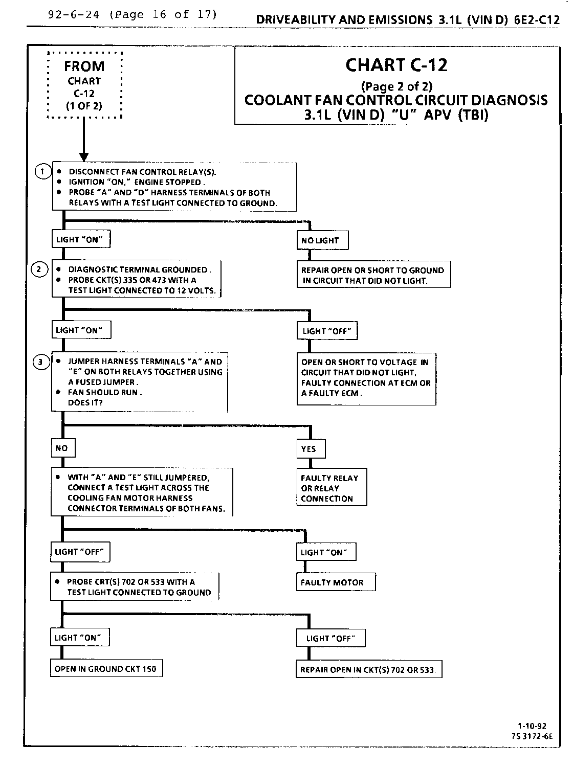
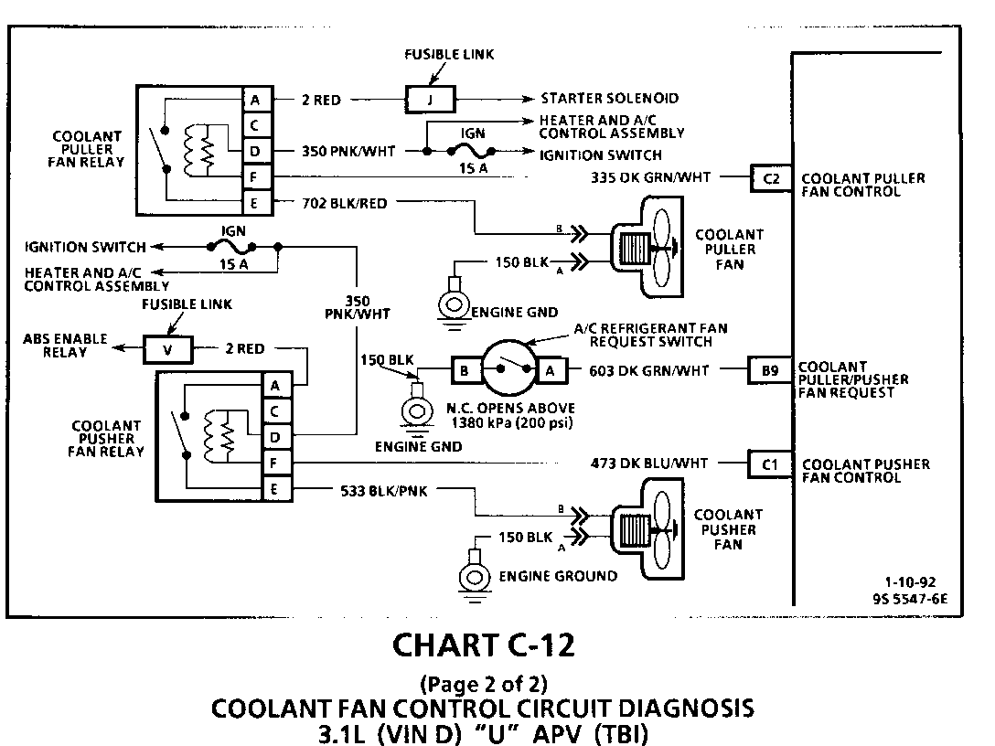
CHART C-12 (Page 2 of 2) COOLANT FAN CONTROL CIRCUIT DIAGNOSIS 3.1L (VIN D) "U" APV (TBI)
Circuit Description:
The electric cooling fan is controlled by the ECM, based on inputs from the coolant temperature sensor, A/C request, A/C refrigerant fan request switch, and vehicle speed. The ECM controls the fan(s) by grounding CKT 335 and CKT 473, which energizes the fan control relay(s). Battery voltage is then supplied to the fan motor(s).
The ECM grounds CKT 335 (Puller Fan Relay), when coolant temperature is approximately 106 C (223 F), or when A/C has been requested, and the A/C refrigerant fan request switch opens with high A/C pressure, about 200 psi (1380 kPa).
The Pusher Fan Relay is grounded by the ECM when coolant temperature is approximately 110 C (217 F). and/or puller fan is "ON" for a/c pressure.
Test Description: Number(s) below refer to circled number(s) on the diagnostic chart.
1. 12 volts should be available to both terminals "A" & "D", when the ignition is "ON."
2. This test checks the ability of the ECM to ground CKT 335 and CKT 473. The "Service Engine Soon" light should also be flashing at this point. If it isn't flashing, see CHART A-2.
3. This test checks to see if the coolant puller and pusher fan relay (CKTS 702 and 533) are open. Jumpering Terminals "A" and "E" bypasses the relay, which should cause the fans to run if fan motors and wiring are OK.
Diagnostic Aids:
If the owner complained of an engine overheating problem, it must be determined if the complaint was due to an actual boil over, or the hot light, or temperature gage indicated over heating.
If the gage or light indicates overheating but no boil over is detected, the gage circuit should be checked. The gage or sending unit accuracy can also be checked by comparing the coolant sensor reading using a Tech 1 Scan tool and comparing its reading with the gage reading.
If the engine is actually overheating and the gage indicates overheating but the cooling fan is not coming "ON" and the Tech 1 Scan tool indicates normal readings, the coolant sensor has probably shifted out of calibration and should be replaced.
If the engine is overheating and the cooling fan is "ON," the cooling system should be checked.
General Motors bulletins are intended for use by professional technicians, not a "do-it-yourselfer". They are written to inform those technicians of conditions that may occur on some vehicles, or to provide information that could assist in the proper service of a vehicle. Properly trained technicians have the equipment, tools, safety instructions and know-how to do a job properly and safely. If a condition is described, do not assume that the bulletin applies to your vehicle, or that your vehicle will have that condition. See a General Motors dealer servicing your brand of General Motors vehicle for information on whether your vehicle may benefit from the information.
