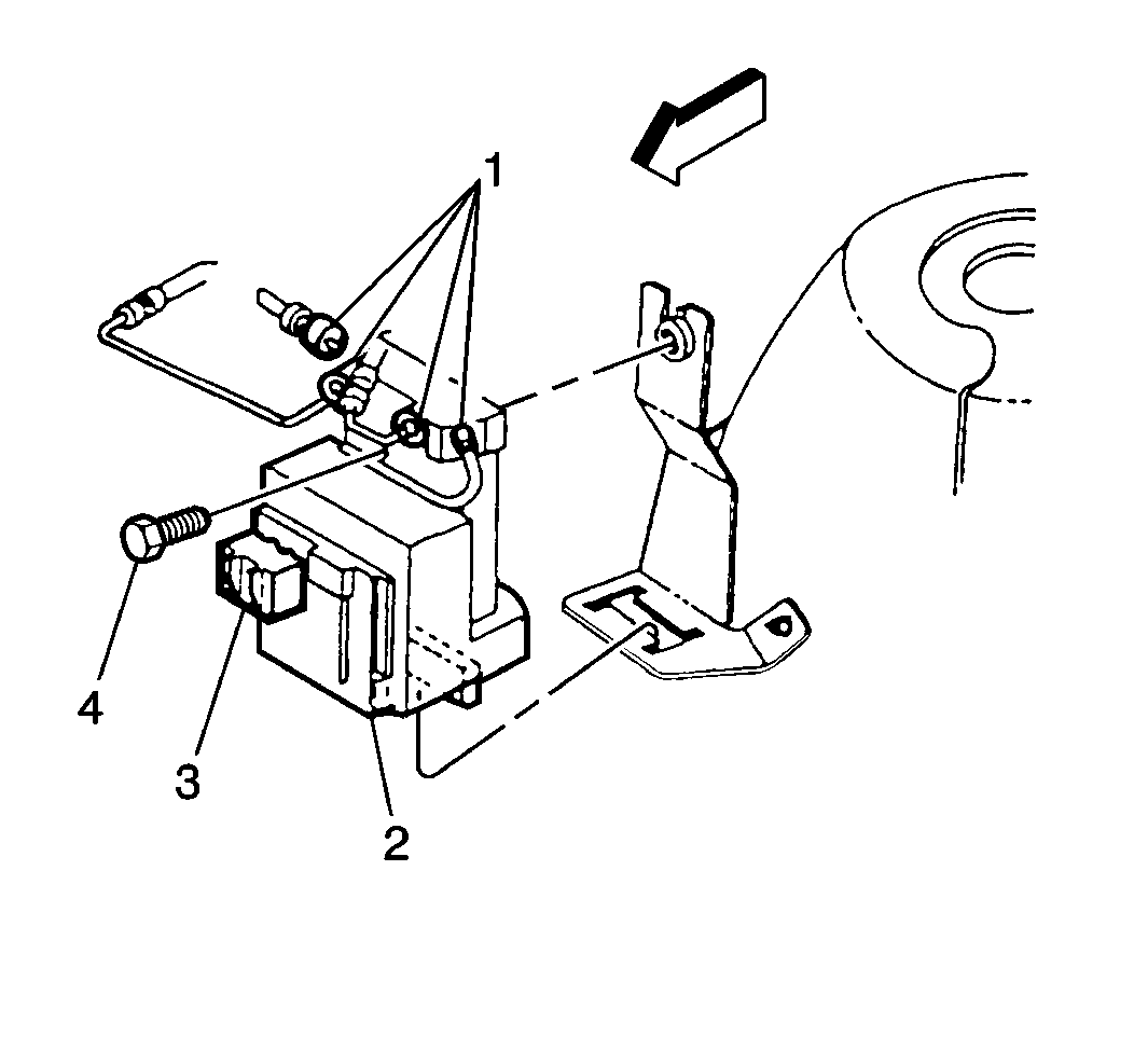
Removal Procedure

- Remove the TCS motor pack
4-way electrical connector (3) from TCS modulator pack (2).
- Use the following procedure in order to remove four brake pipes
(1):
| 2.1. | Place a shop cloth on top of the TCS motor pack in order to catch
any dripping fluid. |
| 2.2. | Do not allow any brake fluid to enter the bottom of the motor
pack or the electrical connectors. |
| 2.3. | Remove the two pipes running from the ABS hydraulic modulator. |
| 2.4. | Remove the two pipes running to the front wheel brakes. |
| 2.5. | Plug the open brake pipes in order to prevent fluid loss and contamination. |
- Remove the bolt (4) attaching the TCS hydraulic modulator/motor
pack assembly (2) to the mounting bracket.
- Lean the TCS hydraulic modulator/motor pack assembly (2) forward
and remove from the bracket.
Installation Procedure

- Install the TCS hydraulic
modulator/motor pack assembly (2) into the bracket, making sure the unit is
properly seated all the way down into the bracket.
Notice: Use the correct fastener in the correct location. Replacement fasteners
must be the correct part number for that application. Fasteners requiring
replacement or fasteners requiring the use of thread locking compound or sealant
are identified in the service procedure. Do not use paints, lubricants, or
corrosion inhibitors on fasteners or fastener joint surfaces unless specified.
These coatings affect fastener torque and joint clamping force and may damage
the fastener. Use the correct tightening sequence and specifications when
installing fasteners in order to avoid damage to parts and systems.
- Install the bolt
(4) attaching the TCS hydraulic modulator/motor pack assembly (2) to the mounting
bracket.
Tighten
Tighten the bolt (4) to 9 N·m (80 lb in).
- Install the four brake pipes (1) to the TCS hydraulic modulator/motor
pack assembly (2).
- Clean up any and all excess brake fuild drippings.
- Install the 4-way TCS motor pack electrical connector (3).
- Bleed the system. Refer to
Hydraulic Brake System Bleeding
in Brakes.


