Removal Procedure
- Raise and suitably support the vehicle. Refer to Lifting and Jacking the Vehicle in General Information.
- Place alignment marks on the cross groove joint and universal joint flange.
- Remove the cross joint retaining bolts.
- Support the propeller shaft assembly.
- Remove the propeller shaft. Refer to Two-Piece Propeller Shaft Replacement in this section.
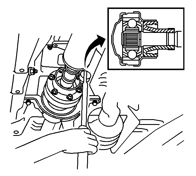
- Using a hammer and chisel, unstake the universal joint flange retaining nut.
- Using a vise to hold the front flange, remove the nut and plate washer.
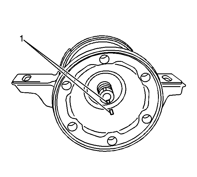
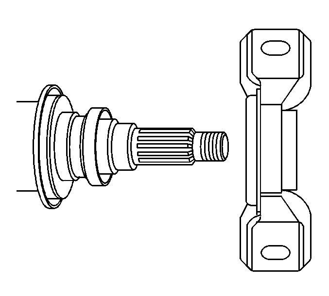
- Place alignment marks on the universal joint flange (1).
- Using a two jaw puller, remove the universal joint flange.
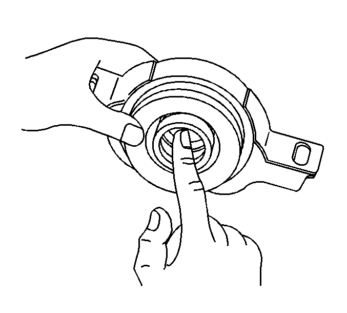
- Remove the center support bearing and plate washer from the propeller shaft.
- Turn the bearing by hand, check the bearing for smooth rotation.
- Inspect the center bearing for wear or damage.
- Inspect the seals for cracks or distortion.
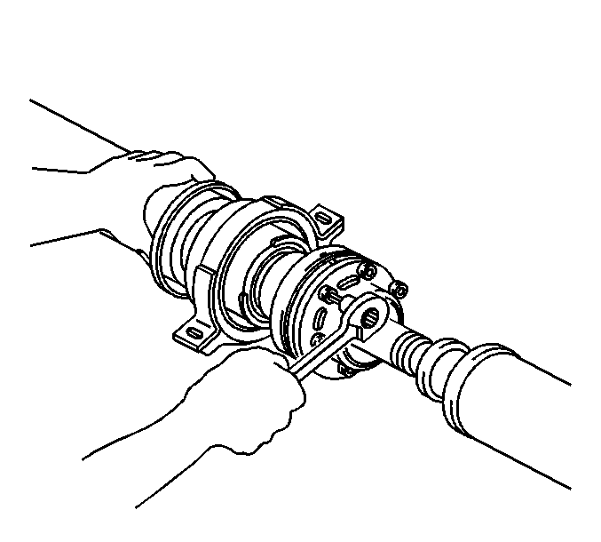
Important: Place a shop rag or equivalent into the inside of the cross groove joint cover so the boot does not touch the inside of the cross groove joint cover after the bolts have been removed.
Installation Procedure
- Install the center support bearing, then the plate washer.
- Align the alignment marks (1) on the universal joint flange and the intermediate shaft.
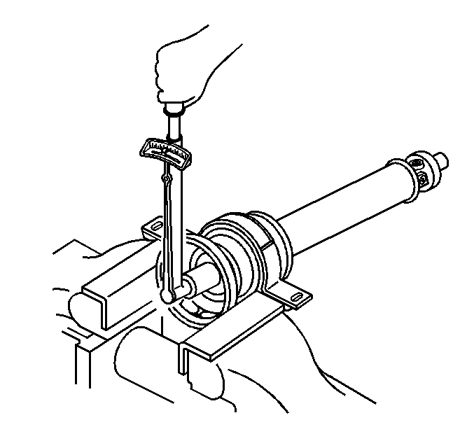
- Using a new nut and plate washer, press the bearing into position by tighten the nut as follows:
- Tighten the nut to 181 N·m (134 lb ft).
- Loosen the nut.
- Retighten the nut to 69 N·m (51 lb ft).
- Using a hammer and chisel, stake the retaining nut.
- Inspect the cross groove joint.
- Align the alignment marks on the intermediate shaft and rear propeller shaft, then install the two washers and 6 bolts temporarily.
- Install the propeller shaft. Refer to Two-Piece Propeller Shaft Replacement .
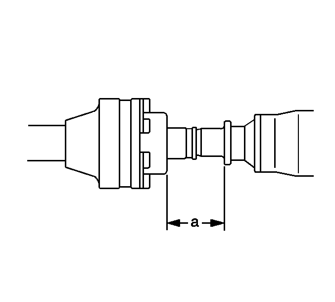
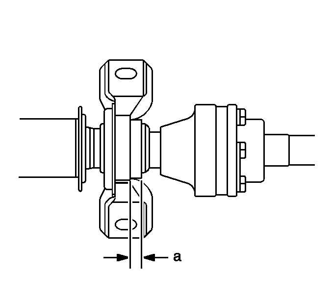
- Adjust the dimension (a) between rear side of cover and the shaft to 57.5-58.5 mm (2.264-2.303 in).
- Adjust the center bearing dimension (a) to 11.5 -13.5 mm (.453 -.531 in).
- Tighten the center bearing retaining bolts.
- Ensure that the center line of the center bearing bracket is at right angles of the propeller shaft.
- Lower the vehicle.
Notice: Use the correct fastener in the correct location. Replacement fasteners must be the correct part number for that application. Fasteners requiring replacement or fasteners requiring the use of thread locking compound or sealant are identified in the service procedure. Do not use paints, lubricants, or corrosion inhibitors on fasteners or fastener joint surfaces unless specified. These coatings affect fastener torque and joint clamping force and may damage the fastener. Use the correct tightening sequence and specifications when installing fasteners in order to avoid damage to parts and systems.
Tighten
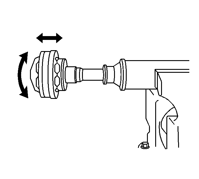
The joint should move smoothly in all directions shown. Check for damage or grease leakage from the boot. If a problem is found, replace the rear propeller shaft.
Important: Do not tighten the center support bearing retaining bolts during installation.
Tighten
Tighten the cross groove joint bolts to 27 N·m (20 lb ft).
Important: The vehicle should be unloaded for the following steps.
Select one of the following spacers:
| • | 3.6 mm (0.142 in) |
| • | 4.5 mm (0.177 in) |
| • | 6.5 mm (0.256 in) |
| • | 9.0 mm (0.354 in) |
Tighten
Tighten the center bearing bolts to 37 N·m (27 lb ft).
