Auxiliary Intake Air Control Solenoid Inspection with Scan Tool
The auxiliary intake air control solenoid is operated by the powertrain control module (PCM). The PCM supplies a ground path to the solenoid control circuit using an internal solid state device called a driver. When the PCM commands the solenoid ON, the voltage on the control circuit should be near zero or low. When the PCM commands the solenoid OFF, the voltage on the control circuit should be near battery voltage or high. When the solenoid is energized, manifold vacuum is applied to the vacuum motor and the auxiliary inlet air duct door is closed.
Test Description
The numbers below refer to the step numbers in the diagnostic table.
-
This step verifies that the vent port of the solenoid is open.
-
This step verifies that the vent port of the solenoid is now closed.
-
This step tests the control circuit of the solenoid.
Step | Action | Value(s) | Yes | No |
|---|---|---|---|---|
Schematic Reference: Engine Controls Schematics | ||||
1 |
Is the resistance within the specified range? | 37-44 ohms at 20°C (68°F) | Go to Step 2 | Go to Step 10 |
Did the vacuum indicated by the vacuum pump remain at zero? | 51 kPa (15 in Hg) | Go to Step 3 | Go to Step 10 | |
Did the vacuum indicated by the vacuum pump reach the specified value? | 51 kPa (15 in Hg) | Go to Step 4 | Go to Step 5 | |
4 | Command the intake air control solenoid OFF with the scan tool. Did the vacuum indicated by the vacuum pump drop to zero? | -- | System OK | Go to Step 9 |
5 |
Does the test lamp illuminate? | -- | Go to Step 6 | Go to Step 8 |
6 |
Does the test lamp illuminate? | -- | Go to Step 10 | Go to Step 7 |
Did you find and correct a condition? | -- | Go to Step 3 | Go to Step 11 | |
8 | Repair the open in the ignition positive voltage circuit. Refer to Wiring Repairs in Wiring Systems. Did you complete the repair? | -- | Go to Step 3 | -- |
9 |
Did you find and correct a condition? | Go to Step 3 | Go to Step 11 | |
10 | Replace the auxiliary intake air control solenoid. Refer to Auxiliary Intake Air Control Solenoid Replacement . Did you complete the replacement? | -- | Go to Step 2 | -- |
11 | Replace the PCM. Refer to Powertrain Control Module Replacement . Did you complete the replacement? | -- | Go to Step 3 | -- |
Auxiliary Intake Air Control Solenoid Inspection w/o Scan Tool
The auxiliary intake air control solenoid is operated by the powertrain control module (PCM). The PCM supplies a ground path to the solenoid control circuit using an internal solid state device called a driver. When the PCM commands the solenoid ON, the voltage on the control circuit should be near zero or low. When the PCM commands the solenoid OFF, the voltage on the control circuit should be near battery voltage or high. When the solenoid is energized, manifold vacuum is applied to the vacuum motor and the auxiliary inlet air duct door is closed.
- Disconnect the electrical connector of the intake air control solenoid.
- Use a DMM in order the measure the solenoid resistance value.
- Replace the solenoid if the resistance is not within the specified range. Refer to Auxiliary Intake Air Control Solenoid Replacement .
- Use a DMM in order the check for continuity between each solenoid terminal and the solenoid housing.
- Replace the intake air control solenoid if the resistance is not within specification. A shorted solenoid may cause damage to the PCM.
- Blow air through the inboard port of the intake air control solenoid. Air has to flow freely through the vent port and NOT out of the outboard port.
- Replace the solenoid if either of the following conditions is observed. Refer to Auxiliary Intake Air Control Solenoid Replacement .
- Apply battery voltage across the solenoid terminals.
- Blow air through the inboard port of the solenoid. Air should flow through the solenoid and out of the outboard port.
- Replace the solenoid if the solenoid fails any of the tests. Refer to Auxiliary Intake Air Control Solenoid Replacement .
- Connect the electrical connector of the intake air control solenoid.
- Start the engine.
- Inspect that the intake air control solenoid is ON.
- If the solenoid is not energized, disconnect the solenoid electrical connector and connect a test lamp across the terminals of the solenoid circuit.
- If the test lamp illuminated, replace the solenoid. Refer to Auxiliary Intake Air Control Solenoid Replacement .
- If the test lamp did not illuminate, inspect for the following conditions:
- Repair any electrical circuit conditions as necessary. Refer to Wiring Repairs in Wiring Systems.
- If you did not find and repair an electrical condition, replace the PCM. Refer to Powertrain Control Module Replacement .
Caution: Do not breathe the air through the EVAP component tubes or hoses. The fuel vapors inside the EVAP components may cause personal injury.
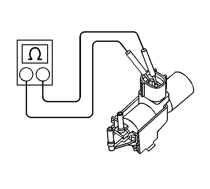
Measure
The resistance should be between 37-44 ohms at 20°C (68°F).
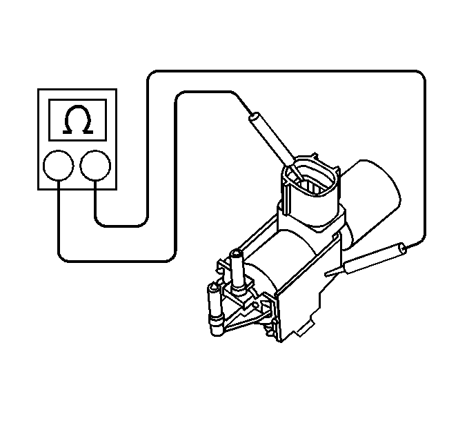
Measure
The DMM has to read infinite (OL).
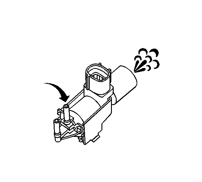
| • | Air flows from the inboard port out through the outboard port. |
| • | Air does not flow from the inboard port out through the vent port. |
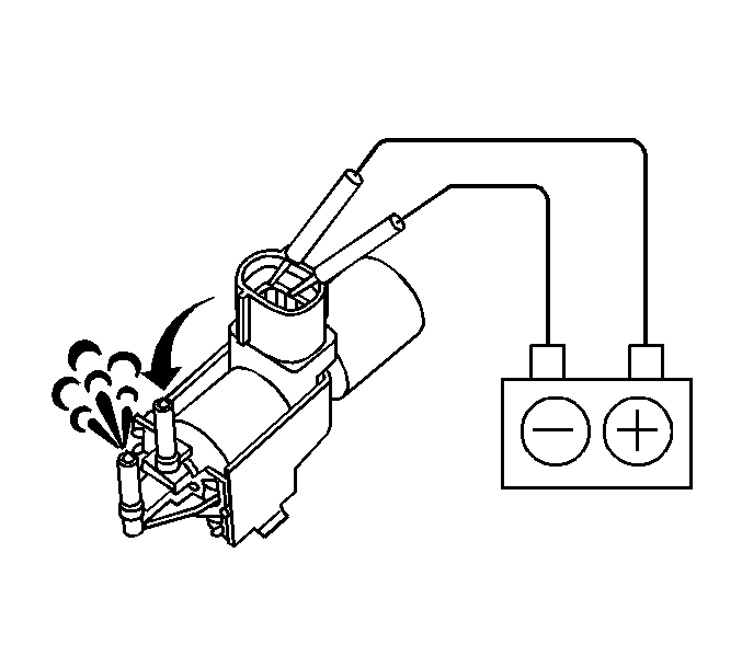
| • | Inspect for an open in the ignition positive voltage supply to the solenoid. |
| • | Inspect for an open or a short to voltage in the solenoid control circuit. |
Vacuum Check Valve Inspection
Tools Required
J 23738-A Hand Vacuum Pump
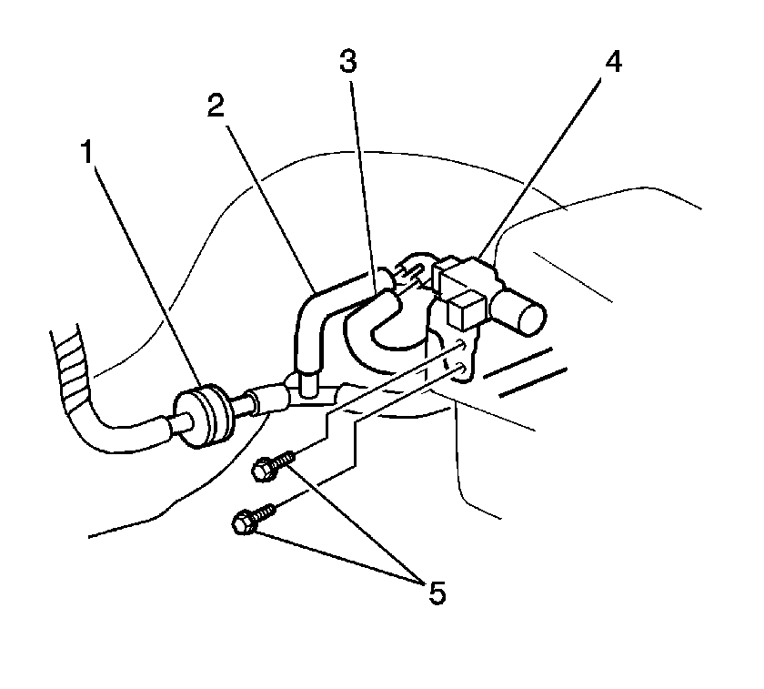
- Remove the vacuum check valve (1) from the auxiliary intake air system.
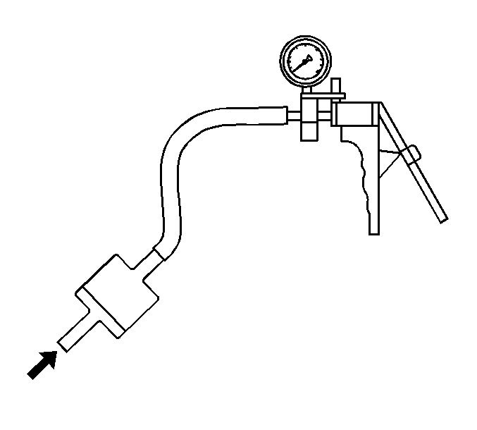
- Connect the J 23738-A or an equivalent hand vacuum pump to the intake manifold side of the vacuum check valve.
- Attempt to apply a vacuum of 34 kPa (254 mm Hg, 10 in. Hg) to the vacuum check valve.
- The check valve SHOULD NOT hold vacuum pressure.
- Disconnect the J 23738-A or an equivalent hand vacuum pump from the check valve.
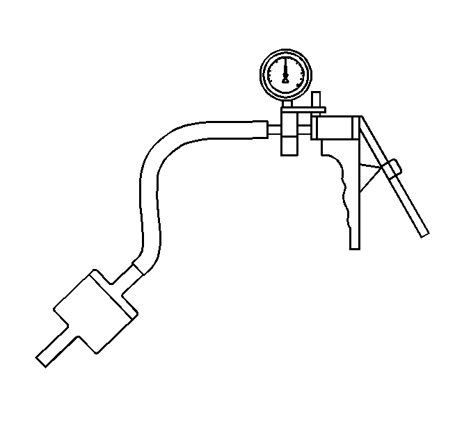
- Connect the J 23738-A or an equivalent hand vacuum pump to the other side of the check valve.
- Apply a vacuum of 34 kPa (254 mm Hg, 10 in. Hg) to the vacuum check valve.
- The check valve SHOULD hold vacuum pressure.
- Replace the vacuum check valve if the valve failed either of the tests above.
- Install the vacuum check valve (1).
- Ensure that the check valve (1) is installed with the side that holds vacuum toward the intake air control solenoid (3).

Auxiliary Intake Air Door Inspection
Tools Required
J 23738-A Hand Vacuum Pump
- In order to view the operation of the auxiliary intake air door, remove the air cleaner cover and air cleaner element.
- Observe that the auxiliary intake air door is OPEN.
- If the intake air door is closed test for a faulty intake air control solenoid.
- Disconnect the vacuum hose to the auxiliary intake air door motor.
- Observe that the auxiliary intake air door is OPEN.
- Replace the air cleaner assembly if the intake air door is closed. Refer to Air Cleaner Assembly Replacement .
- Connect the J 23738-A or an equivalent hand vacuum pump to the intake air door motor.
- Apply a vacuum of 34 kPa (254 mm Hg, 10 in. Hg) to the intake air door motor.
- The intake air door motor should CLOSE and HOLD vacuum.
- Replace the air cleaner assembly if the intake air door fails the above test. Refer to Air Cleaner Assembly Replacement .
- Connect the J 23738-A or an equivalent hand vacuum pump to the vacuum storage chamber on the air cleaner upper assembly.
- Apply a vacuum of 34 kPa (254 mm Hg, 10 in. Hg) to the storage chamber.
- The vacuum chamber should HOLD the vacuum pressure.
- Replace the air cleaner assembly if the vacuum storage chamber looses pressure. Refer to Air Cleaner Assembly Replacement .
