GM Service Manual Online
For 1990-2009 cars only

EVAP System Function

The evaporative emission (EVAP) control system limits fuel vapors from escaping into the atmosphere. The fuel tank vapors are allowed to move from a sealed fuel tank, due to pressure in the tank , through a vapor pipe into the EVAP canister. Carbon in the canister absorbs and stores the fuel vapors. Excess pressure is vented through the vent line and vent valve to atmosphere. The EVAP canister stores the fuel vapors until the engine is able to use them.

EVAP System Operation

When the engine is operating in Closed Loop and the engine coolant temperature is more than 74°C (165°F), the powertrain control module (PCM) initiates purging of the stored fuel vapors. In order to purge the fuel system vapors, the PCM commands the purge valve ON, OPEN, allowing engine vacuum to be applied to the EVAP canister. With the EVAP vent valve OFF, OPEN, fresh air will be drawn through the EVAP canister air filter and vent valve into the EVAP canister. Manifold vacuum continues to pull fresh air through the canister pulling fuel vapors from the carbon. The air/fuel vapor mixture passes through the purge line and purge valve into the intake manifold to be consumed during the normal combustion process.


Object Number: 1459489  Size: SH
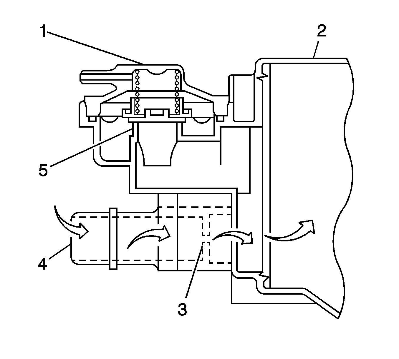
(1)Fill Limiter Vent Valve (FLVV)
(2)EVAP Canister
(3)Restrictor Orifice
(4)On-Board Refueling Vapor Recovery (ORVR) Vent Line Inlet Port
(5)Vent Control Valve

Atmospheric pressure (4) is allowed into the canister in order to ensure that purge flow is consistently maintained whenever purge vacuum is applied to the canister. The PCM will change the duty ratio cycle of the purge solenoid valve, controlling the purge flow volume. Purge flow volume is determined by manifold pressure, the purge solenoid duty ratio cycle, and the restrictor passage (3) in the canister. The restrictor passage prevents a large volume of vapor from suddenly entering the intake manifold and affecting the airfuel ratio.

EVAP System Components

The EVAP control system consists of the following components:

EVAP Canister

The EVAP canister is filled with carbon pellets used to absorb and store fuel vapors. Fuel vapors are stored in the EVAP canister until the PCM determines that the vapor can be consumed in the normal combustion process.

EVAP Canister Purge Solenoid Valve

The EVAP canister purge solenoid valve controls the flow of fuel vapors from the EVAP system to the intake manifold. The purge solenoid valve is low side controlled by the PCM, using a pulse width modulated (PWM) or duty cycle circuit. The purge solenoid valve is also opened during some portions of the EVAP system testing.

EVAP Vacuum Leak Pump Assembly


Object Number: 1459490  Size: SH
(1)Leak Pump Assembly Electrical Connector
(2)EVAP Canister Vent Solenoid Valve
(3)Fresh Air Inlet Port
(4)EVAP Canister Port
(5)O-ring Seal
(6)Vacuum Pump
(7)Vacuum Leak Pump Motor
(8)FTP Sensor

The EVAP vacuum leak pump assembly contains the fuel tank pressure (FTP) sensor, the canister vent solenoid valve, and an electric motor driven vacuum pump. The vacuum pump provides pressure for leak testing when the engine has been OFF for at least five hours and the engine coolant temperature (ECT) is less than 35°C (95°F). If the ECT is greater than 35°C (95°F) after five hours, the diagnostic will wait an additional two  hours. If the ECT is still greater than 35°C (95°F) after seven hours, the diagnostic will wait an additional two and a half hours. The pump assembly also has several internal filters and a 0.5 mm (0.020 inch) reference orifice. The reference orifice provides controlled movement of the pressure within the system, enabling the FTP sensor to accurately monitor system performance. The complete pump assembly is mounted on the EVAP canister, eliminating the need for additional hoses or lines for connections.

EVAP Vacuum Leak Pump

The vacuum pump is driven by a 12 volt brush less motor that is high side controlled by the PCM. The pump is a vane type design capable of producing at least 33.50 mm Hg (18 in H2O) of vacuum pressure.

EVAP Canister Vent Solenoid Valve


Object Number: 1456208  Size: SH
(1)Fuel Tank Pressure (FTP) Sensor
(2)EVAP Vacuum Leak Pump Assembly
(3)EVAP Canister Vent Valve Port to Canister

The EVAP canister vent solenoid valve is an integral part of the EVAP vacuum leak pump assembly (2). The vent valve controls the flow of clean air into or out of (3) the EVAP canister. The vent valve is normally open. Under certain conditions the PCM commands the vent valve closed in order to seal the EVAP system for leak diagnosis.

Fuel Tank Pressure (FTP) Sensor

The fuel tank pressure (FTP) sensor, measures the difference between the fuel tank and outside air pressure. The FTP sensor is an integral part of the EVAP vacuum leak pump assembly. The PCM provides a 5-volt reference and a ground to the FTP sensor. The FTP sensor provides a signal voltage back to the PCM that can vary between 0.1 and 4.9 volts. As the fuel tank pressure increases, the FTP sensor voltage decreases, as the fuel tank pressure decreases the FTP sensor voltage increases. High pressure = high voltage. Low pressure vacuum = low voltage.

Fuel Tank Vapor Space

FTP mmHg

FTP Signal Voltage

Pressure

Positive Value

High

No Pressure

Near Zero

3.0-3.6V

Vacuum

Negative Value

Low

EVAP Filter


Object Number: 1456195  Size: SH

The EVAP filter (1) is attached to the EVAP canister and provides clean air for the purging of fuel vapors. Excess pressure in the EVAP system also flows thru the EVAP filter and is released into the atmosphere. The filter element is a sealed unit and is not serviceable separately.
EVAP System Diagnostic Strategy


Object Number: 1459492  Size: SH
(1)Air and Vapor
(2)Air
(3)Filters
(4)EVAP Canister Vent Solenoid Valve
(5)Filter
(6)Reference Orifice
(7)Fuel Tank Pressure (FTP) Sensor
(8)Vacuum Leak Pump Motor

During normal EVAP system operation the EVAP canister vent solenoid valve (4) is OPEN allowing the flow of fresh air (2) into the EVAP canister. If the EVAP canister purge valve is also OPEN, the fresh air will mix with vapors stored in the canister and flow (1) from the canister to the intake manifold. The FTP sensor (7) is used to monitor system operation and the vacuum leak pump (8) provides vacuum pressure for leak detection.

The PCM performs several diagnostic tests in order to determine if the EVAP system is functioning correctly or leaking. When certain operating criteria are met before engine shutdown, the PCM will run a comprehensive series of tests when the following conditions are met:

    • Five hours have elapsed after the engine was turned Off
    • Altitude is less than 2,400 meters (8,000 feet)
    • Battery voltage is more than 10.5 volts
    • Engine coolant temperature is between 4-35°C (40-95°F)
    • Intake air temperature is between 4-35°C (40-95°F)
    • The ignition remains OFF for the duration of the test

The internal timer responsible for the sequencing of the EVAP system diagnostic routine is monitored by the PCM. If the PCM detects a fault in the internal timer, a DTC P2610 will set.

Vacuum Leak Pump and Reference Orifice Test

The first two events of the EVAP system diagnostic checks the operation of the vacuum leak pump and for a restriction in the reference orifice. With the purge solenoid and the vent solenoid both OFF, atmospheric pressure should enter the EVAP system and be detected by the FTP sensor. If atmospheric pressure is not detected, the reference orifice may be plugged. During event two, the vacuum leak pump is turned ON and the FTP sensor should indicate negative pressure within a specified value. If the pressure change is too small, a DTC P043E can set. If the pressure change is too large, a DTC P043F can set. If atmospheric pressure is measured in event one, but no negative pressure is measured in event two, an inoperative vacuum leak pump is indicated, and a DTC P2401 can set. If there is a sudden large increase in negative pressure when the pump is turned ON, a stuck on vent solenoid may be indicated and a DTC P2419 can set.

Diagnostic Event Sequence

Event One

Event Two

EVAP Purge Solenoid

OFF/CLOSED

OFF/CLOSED

EVAP Vent Solenoid

OFF/OPEN

OFF/OPEN

Vacuum Leak Pump

OFF

ON

FTP Sensor

Atmospheric Pressure

Small Negative Pressure Change

Large Leak test

Event three tests for a large leak in the EVAP system. The PCM commands the EVAP vent valve ON, CLOSED, sealing the EVAP system. This allows the vacuum pump to create a large increase in negative pressure. If the expected increase in negative pressure is not achieved, a large leak is indicated and a DTC P0455 can set. If there is no change in pressure when the vent solenoid is turned ON, the vent solenoid may be inoperative and a DTC P2420 can set.

Diagnostic Event Sequence

Event Two

Event Three

EVAP Purge Solenoid

OFF/CLOSED

OFF/CLOSED

EVAP Vent Solenoid

OFF/OPEN

ON/CLOSED

Vacuum Leak Pump

ON

ON

FTP Sensor

Small Negative Pressure Change

Negative Pressure Increase and Hold

Small Leak Test

If the large leak test passes, the PCM will continue to monitor the FTP sensor signal in order to determine if there is small leak. If a specified minimum value is not achieved or the minimum value can not be maintained, a DTC P0456 can set. This diagnostic can detect leaks as small as 0.5 millimeter (0.020 inch) between the fuel fill cap and the purge valve.

Diagnostic Event Sequence

Event Two

Event Three

EVAP Purge Solenoid

OFF/CLOSED

OFF/CLOSED

EVAP Vent Solenoid

OFF/OPEN

ON/CLOSED

Vacuum Leak Pump

ON

ON

FTP Sensor

Small Negative Pressure Change

Negative Pressure Increase and Hold

EVAP Purge Valve Test

In event four of the EVAP system diagnostic, the purge solenoid is turned ON, OPEN, causing a drop in negative pressure. If the FTP sensor does not detect a significant decrease in vacuum pressure, a DTC P0441 will set.

Diagnostic Event Sequence

Event Three

Event Four

EVAP Purge Solenoid

OFF/OPEN

ON/OPEN

EVAP Vent Solenoid

ON/CLOSED

ON/CLOSED

Vacuum Leak Pump

ON

ON

FTP Sensor

Negative Pressure Increase and Hold

Negative Pressure is Released

Final Test

In event five all of the EVAP components return to the same state they were in event one. Because the vacuum pump remained ON in event four, the FTP sensor still detected a small vacuum. Now, with all components OFF, the pressure should return to atmosphere, indicating there are is no blockage or restrictions in the EVAP system.

Diagnostic Event Sequence

Event Four

Event Five

EVAP Purge Solenoid

ON/OPEN

OFF/CLOSED

EVAP Vent Solenoid

ON/CLOSED

OFF/OPEN

Vacuum Leak Pump

ON

OFF

FTP Sensor

Very Small Negative Pressure

Atmospheric Pressure

FTP Sensor Monitor

The performance of the FTP sensor is monitored continuously and regularly. The FTP sensor signal circuit is continuously monitored and DTC P0450, P0452, or P0453 will set if an out of range voltage is detected. DTC P0451 diagnostic monitors the FTP sensor signal voltage for a fixed or skewed value.