Throttle Body Assembly Replacement FWD
Removal Procedure
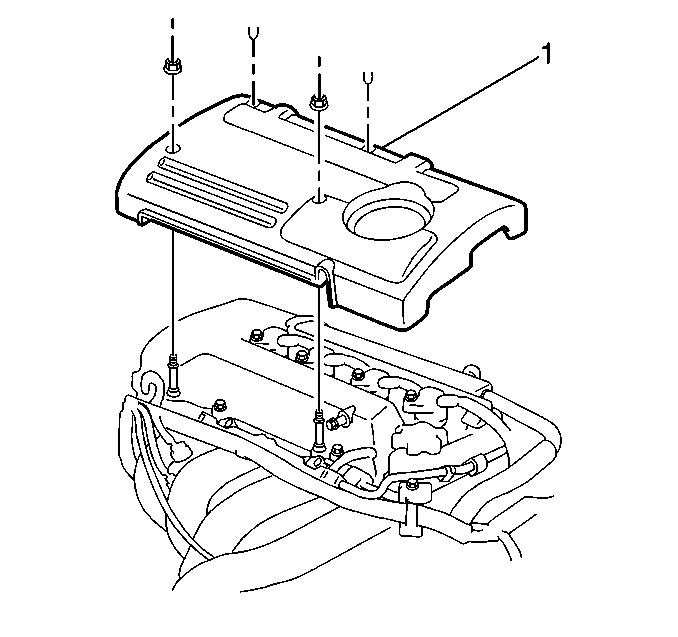
- Remove the 2 nuts and the 2 retainers from the engine cover (1).
- Remove the engine cover (1) from the engine.
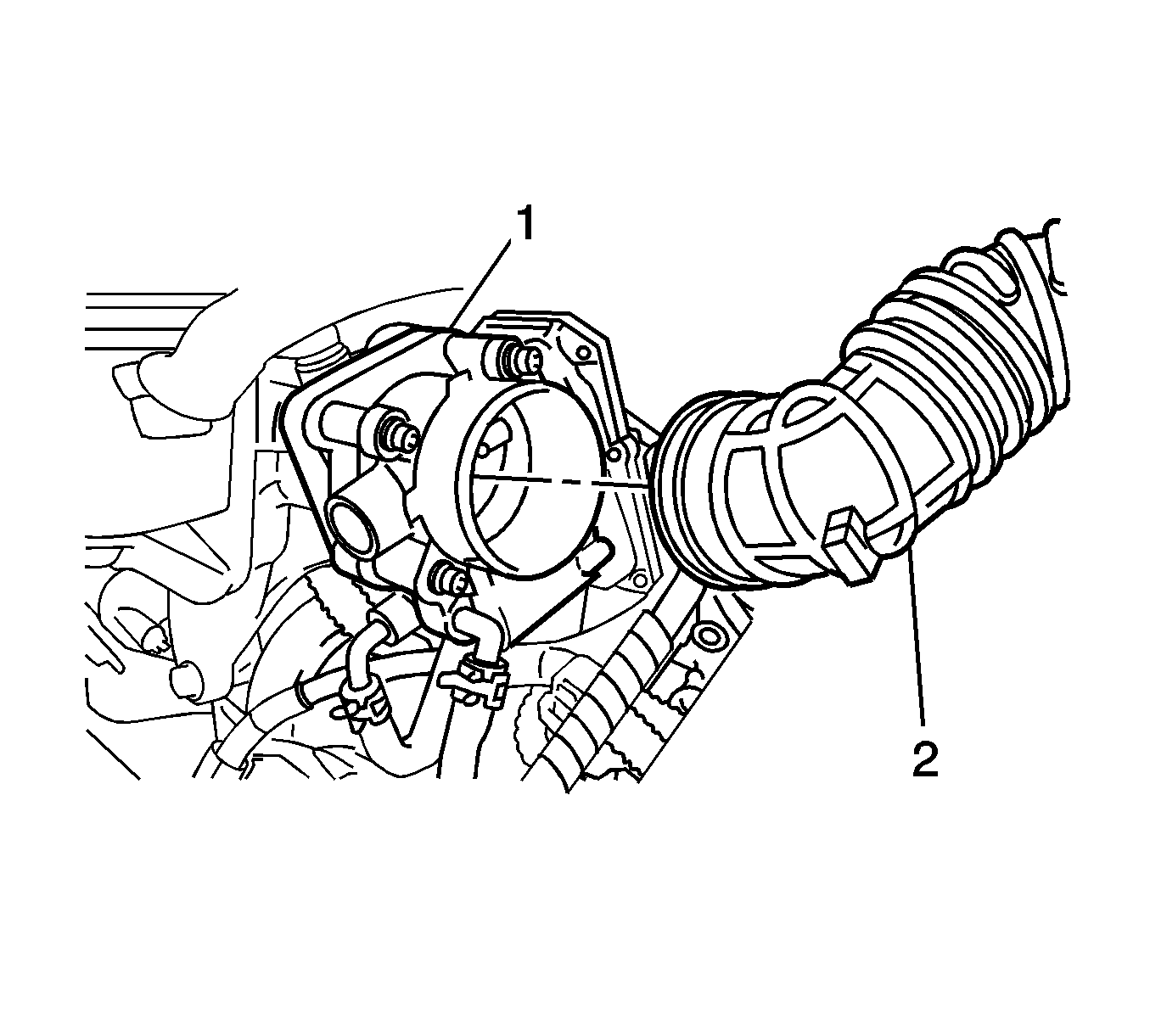
- Loosen the clamp and remove the air inlet duct (2) from the throttle body assembly (1).
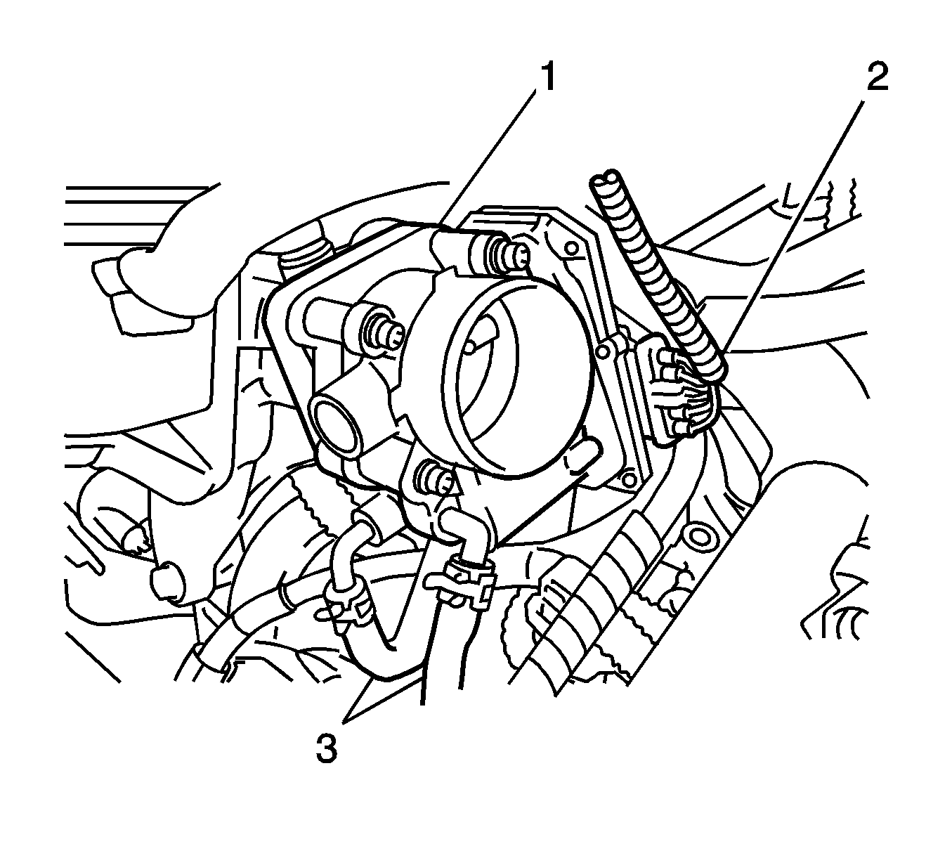
- Disconnect the electrical connector (2) of the throttle actuator control (TAC) module.
- Drain the cooling system. Refer to Cooling System Draining and Filling in Engine Cooling.
- Disconnect the 2 coolant hoses (3) from the throttle body (1).
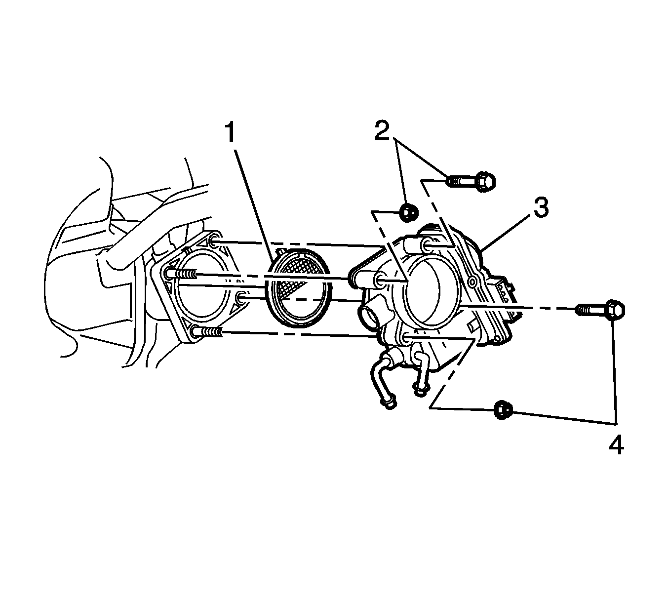
- Remove the upper 2 fasteners (2) and the lower 2 fasteners (4) from the throttle body (3).
- Remove the throttle body (3) and the gasket (1) from the intake manifold.
- Clean any remaining throttle body gasket from the intake manifold.
Installation Procedure
- Install a new throttle body gasket (1) onto the intake manifold.
- Install the throttle body (3) onto the intake manifold.
- Secure the throttle body to the manifold with 4 fasteners (2, 4).
- Connect the 2 coolant hoses (3) to the throttle body (1).
- Connect the TAC module electrical connector (2).
- Install the air inlet duct (2) to the throttle body (1).
- Refill the cooling system. Refer to Cooling System Draining and Filling in Engine Cooling.
- Install the engine cover (1) to the engine.
- Secure the engine cover (1) with the 2 nuts.
- Install the 2 retainers to the engine cover.

Notice: Refer to Fastener Notice in the Preface section.
Install the 4 throttle body fasteners.
Tighten
Tighten the fasteners to 9 N·m (80 lb in).


Tighten
Tighten the fasteners to 7 N·m (62 lb in).
Throttle Body Assembly Replacement AWD
Removal Procedure
- Remove the 2 nuts and the 2 retainers from the engine cover (1).
- Remove the engine cover (1) from the engine.
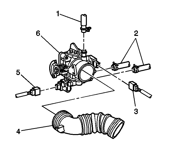
- Remove the air inlet duct (4) from the throttle body assembly (6).
- Remove the positive crankcase ventilation (PCV) breather hose (1).
- Remove the throttle position (TP) sensor connector (3).
- Rotate the throttle lever and disconnect the accelerator cable and the throttle valve cable, if equipped.
- Disconnect the electrical connector (5) of the idle air control (IAC) valve.
- Drain the cooling system. Refer to Cooling System Draining and Filling in Engine Cooling.
- Remove the 2 coolant hoses (2) from the throttle body.
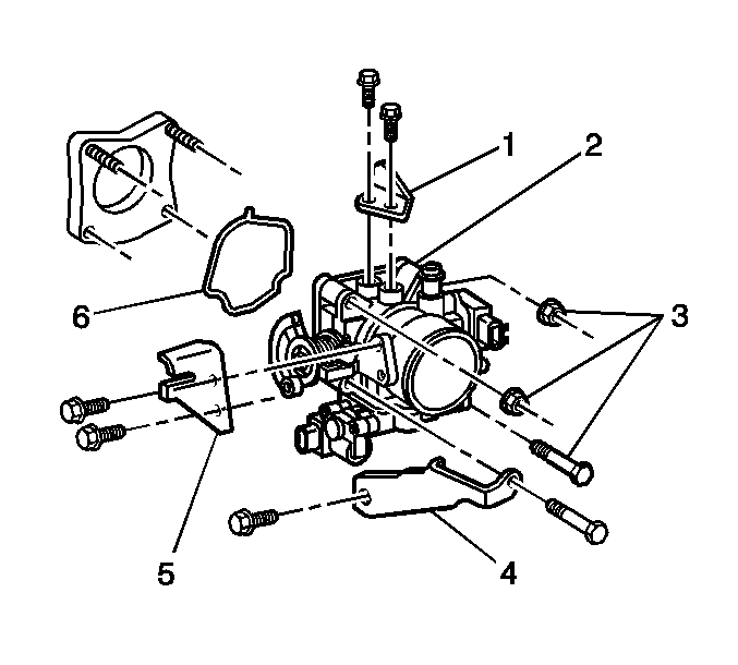
- Remove the 2 bolts and the accelerator control cable bracket (5).
- Remove the 2 fasteners and the throttle body bracket (4).
- Remove the 3 throttle body fasteners (3).
- Remove the 2 fasteners and the manifold support bracket (3).
- Remove the throttle body (2) and the gasket (6) from the intake manifold.
- Clean any remaining throttle body gasket from the intake manifold.

Installation Procedure
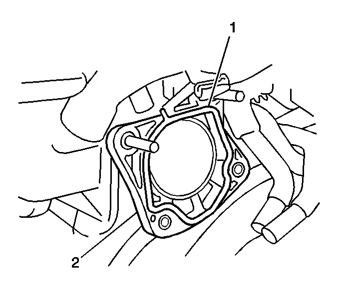
- Install a new throttle body gasket (1) onto the intake manifold (2).
- Install the throttle body (2) onto the intake manifold with the 3 fasteners (3).
- Install the throttle body bracket (4) and the 2 bolts to the throttle body.
- Install the 5 throttle body fasteners.
- Install the manifold support bracket (1) to the throttle body with 2 bolts.
- Install the accelerator control cable bracket (5) to the throttle body with 2 bolts.
- Connect the 2 coolant hoses (2) to the throttle body (6).
- Connect the PCV breather hose (1) to the throttle body (6).
- Connect the IAC valve electrical connector (5).
- Connect the TP sensor electrical connector (3).
- Install the air inlet duct (4).
- Refill the cooling system. Refer to Cooling System Draining and Filling in Engine Cooling.
- Install the engine cover (1) to the engine.
- Secure the engine cover (1) with the 2 nuts.
- Install the 2 retainers to the engine cover.

Notice: Use the correct fastener in the correct location. Replacement fasteners must be the correct part number for that application. Fasteners requiring replacement or fasteners requiring the use of thread locking compound or sealant are identified in the service procedure. Do not use paints, lubricants, or corrosion inhibitors on fasteners or fastener joint surfaces unless specified. These coatings affect fastener torque and joint clamping force and may damage the fastener. Use the correct tightening sequence and specifications when installing fasteners in order to avoid damage to parts and systems.
Tighten
Tighten the fasteners to 30 N·m (22 lb ft).
Install the 2 fasteners.
Tighten
Tighten the fasteners to 30 N·m (22 lb ft).
Install the 2 fasteners.
Tighten
Tighten the fasteners to 13 N·m (10 lb ft).


Tighten
Tighten the fasteners to 7 N·m (62 lb in).
