For 1990-2009 cars only
Stabilizer Shaft Replacement FWD
Removal Procedure
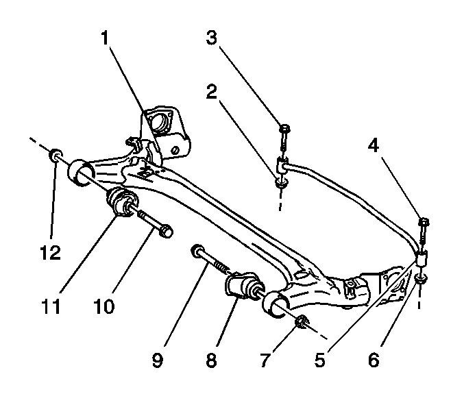
- Remove the 2 nuts (2, 6).
- Remove the 2 bolts (3, 4).
- Remove the stabilizer shaft (5).

Installation Procedure
- Use the mark on the left rear side of the stabilizer shaft (5) in order to position the shaft on the rear axle (1).
- Install the 2 bolts (3, 4) and the 2 nuts (2, 6) in order to retain the shaft to the axle.

Notice: Refer to Fastener Notice in the Preface section.
Tighten
Tighten the nuts and the bolts to 195 N·m (143.8 lb ft).
Stabilizer Shaft Replacement AWD
Removal Procedure
- Remove the rear suspension crossmember and the rear drive module as an assembly. Refer to Rear Suspension Support Crossmember Replacement in Frame and Underbody.
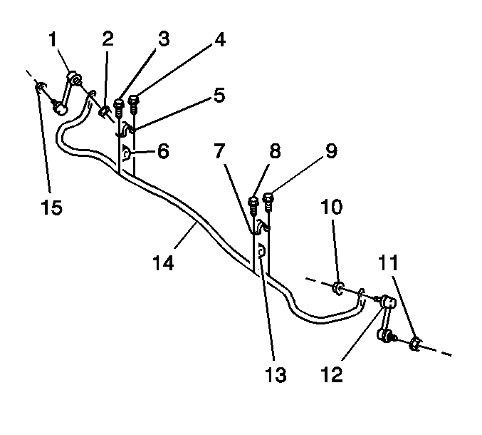
- Use paint in order to place match marks on the stabilizer shaft insulators (6,13) and on the stabilizer shaft (14).
- Remove the 4 bolts (3,4,8,9).
- Remove the 2 stabilizer shaft insulator brackets (5,7).
- Remove the 2 stabilizer shaft insulators (6,13).
- Remove the 2 nuts (2,10) from the link studs.
- Remove the stabilizer shaft from the rear suspension crossmember.

Installation Procedure
- If you are replacing the stabilizer shaft (14) or the insulators (6,13), copy the match marks from the old components to the new components.
- Position the stabilizer shaft on the rear suspension crossmember.
- Install the 2 nuts (2,10) in order to retain the shaft to the link studs.
- Align the match marks and install the insulators to the shaft.
- Install the brackets to the insulators.
- Install the 4 bolts (3,4,8,9) to the brackets.
- Install the rear suspension crossmember and the rear drive module as an assembly. Refer to Rear Suspension Support Crossmember Replacement in Frame and Underbody.

Notice: Refer to Fastener Notice in the Preface section.
Tighten
Tighten the nuts to 44 N·m (32.5 lb ft).
Tighten
Tighten the bolts to 18 N·m (13.3 lb ft).
