Pre-Delivery Inspection (PDI) Information

| Subject: | Pre-Delivery Inspection (PDI) Information |
| Models: | 2006-2008 Pontiac Vibe |
This bulletin is being revised to add the 2008 model year. Please discard Corporate Bulletin Number 05-00-89-059B (Section 00 - General Information).
PDI Concerns
Below are seven specific areas that need to be emphasized due to recognized concerns on delivered vehicles. These items are either unique to this vehicle or have significant impact on initial customer satisfaction.
Radio/Dome Lamp Fuse

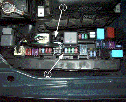
Notice: The 15 A radio/dome lamp fuse MUST be installed in the correct location. A missing or incorrectly installed fuse may result in an inoperative radio, dome lamp and/or remote keyless entry.
All 2007 and 2008 Pontiac Vibe vehicles built on and after January 2, 2007 are shipped with the fuse for the dome lamp/radio disconnected from the underhood fuse block. The 15A fuse is stored in a spare fuse holder (1) forward of the dimmer in the underhood fuse block. To operate the radio, dome lamp and/or remote keyless entry, the fuse must be removed from the spare location and installed into the "dome" fuse location (2). The illustration above shows the 15A fuse installed in the proper location. Refer to the Underhood Fuse Block label to properly locate the Dome fuse location if there is any difficulty in finding the correct location.
Automatic Transmission Shift Interlock (ATSI) Cover
You will find a plastic cap taped to the shifter handle upon delivery of these vehicles to your dealership. This round cap is provided to cover the ATSI override control. The ATSI override is found on the transmission shifter bezel to the right of the shifter. To assure the complete safety and integrity of this system, you MUST install the included cap. To do so, simply insert the cap into the hole until seated.
Vehicle Transportation Tie-Down Underbody Inserts

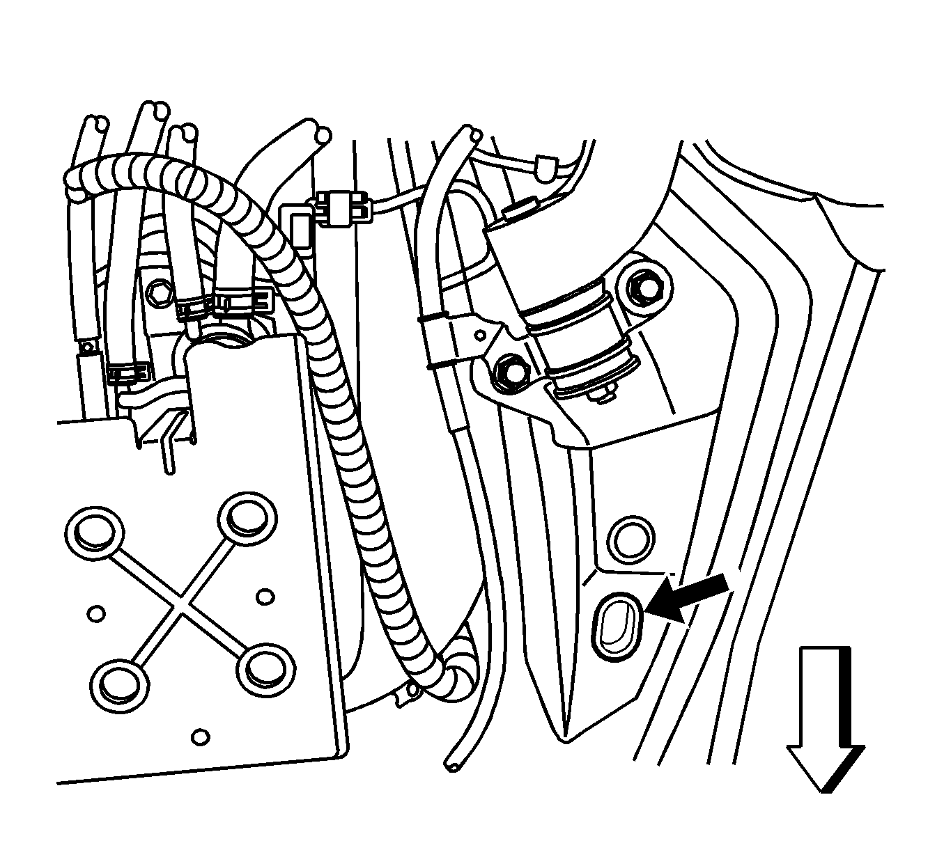
There are two holes located in the vehicle underbody in front of the rear wheels (one hole each side) that are utilized for securing the vehicle during transportation. Two rubber plugs (found in the instrument panel compartment) are included with the vehicle to seal these holes in the underbody. You must install these caps to prevent water intrusion into the unibody which may cause excessive corrosion. Refer to the graphic above which illustrates the passenger side of the vehicle (driver's side similar). The dark arrow indicates the position of the underbody cutout and the outlined arrow indicates the front of vehicle.
Interior Lamps Control
The interior lamps control is located on each overhead light. There is a front and rear dome lamp with a three position switch. The three positions are off, on and door. The vehicle was shipped with the dome lamps in the "off" position to prevent battery discharge. Be sure to set the dome lamps to the "door" position before delivering the vehicle to the customer.
Tire Pressure
Important: Tires MUST be set to the specified inflation pressure during the PRE-DELIVERY INSPECTION (including the spare tire).
Improper tire inflation pressures may result in ride, handling, and/or noise concerns. You MUST measure and adjust the tire inflation pressures during the pre-delivery inspection to the specification on the tire placard, NOT the pressure indicated on the sidewall of the tire. The tire placard is located on the driver's door lock pillar. General Motors vehicles are shipped from the factory with tire inflation pressures from 35 psi (241 kPa) to 41 psi (283 kPa). Tire inflation pressures are set higher at the assembly plants to prevent tire flat spots during transportation and storage.
Tire Pressure Monitoring (TPM) System
To operate the Tire Pressure Monitoring System under normal conditions, the TPM Electronic Control Unit (ECU) must be initialized with the tires at the specified tire inflation pressure. After adjusting all the tires to the specified inflation pressure, please perform following initialization of the TPM ECU at your dealership prior to delivery.
- Adjust all tires to the specified inflation pressure. Refer to the tire placard located on the driver's door lock pillar.
- Turn ON the ignition with the engine OFF.
- Push and hold the Tire Pressure Warning "SET" Switch for 3 seconds until the Low Pressure Warning Light blinks 3 times. Ensure that the Low Tire Pressure Warning Light goes out.
Tip
If the Low Pressure Warning Light does not blink, release the Tire Pressure Warning "SET" Switch and repeat Step 3 again.
While the TPM initialization is in process, the tire pressure will be monitored. The TPM ECU will start to record vehicle data once the initialization is complete and will depend on the vehicle owner's driving patterns, habits, and trip duration. Once the data collection process is complete, the accuracy of tire pressure detection will be increased.
Get-To-Know-You Guide (2007 and 2008 Model Years and U.S Only)
The Get-To-Know-You Guide will be hung from the shifter and should be left in place during PDI. This contains important information for the customer to become familiar with their new vehicle.
