Special Tools
J-43178 Fuel Line Disconnect Tool
Removal Procedure
- Discharge the fuel system pressure. Refer to Fuel Pressure Relief.
- Disconnect the cable from the negative battery terminal. Refer to Battery Negative Cable Disconnection and Connection
- Remove the engine cover. Refer to Engine Cover Replacement.
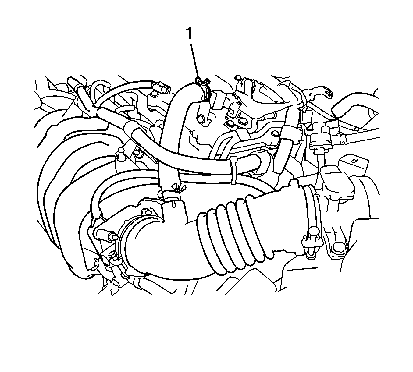
- Disconnect the ventilation hose (1).
- Remove the air cleaner assembly with hose.
- Remove the engine wire.
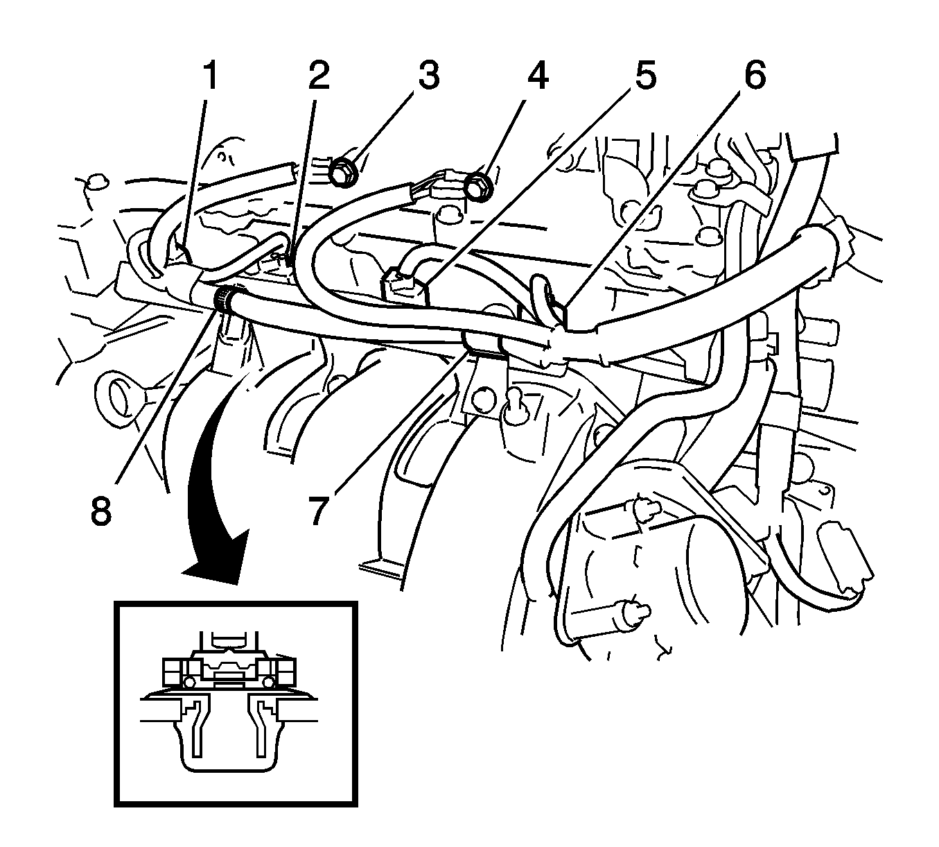
- Remove the 2 bolts and disconnect the ground wire (3, 4).
- Disconnect the 4 fuel injector assembly connectors (1, 2, 5, 6).
- Disconnect the 2 wire harness clamps (7, 8).
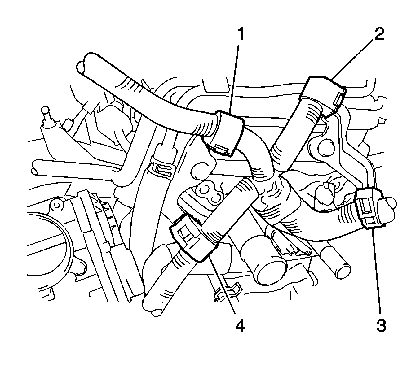
- Disconnect the 4 wire harness clamps (1, 2, 3, 4).
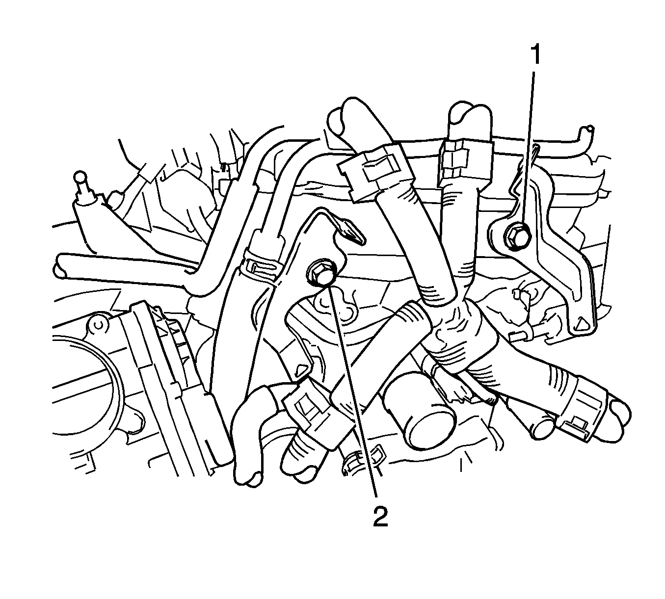
- Remove the 2 bolts (1, 2) and 2 wire harness brackets.
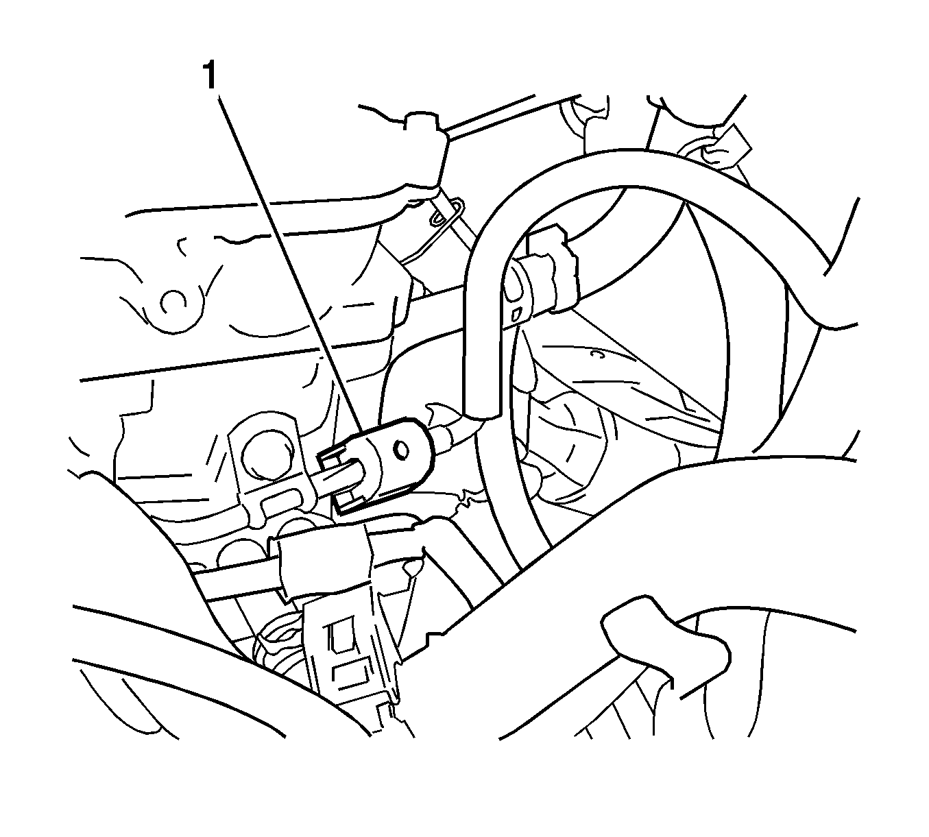
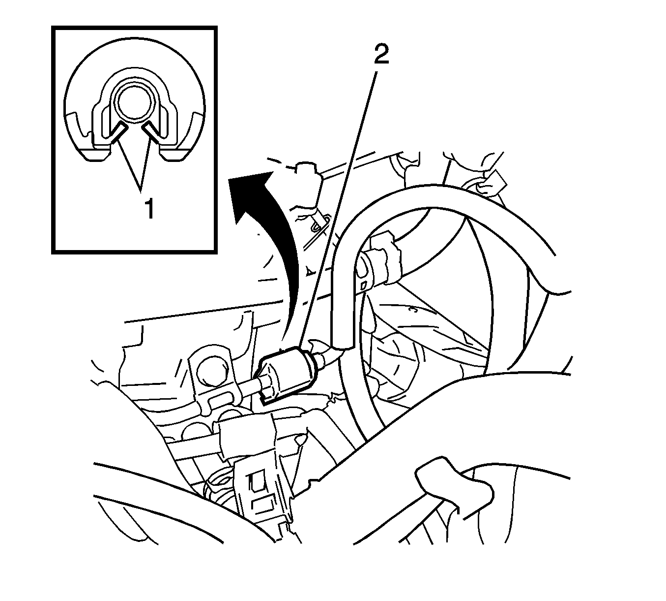
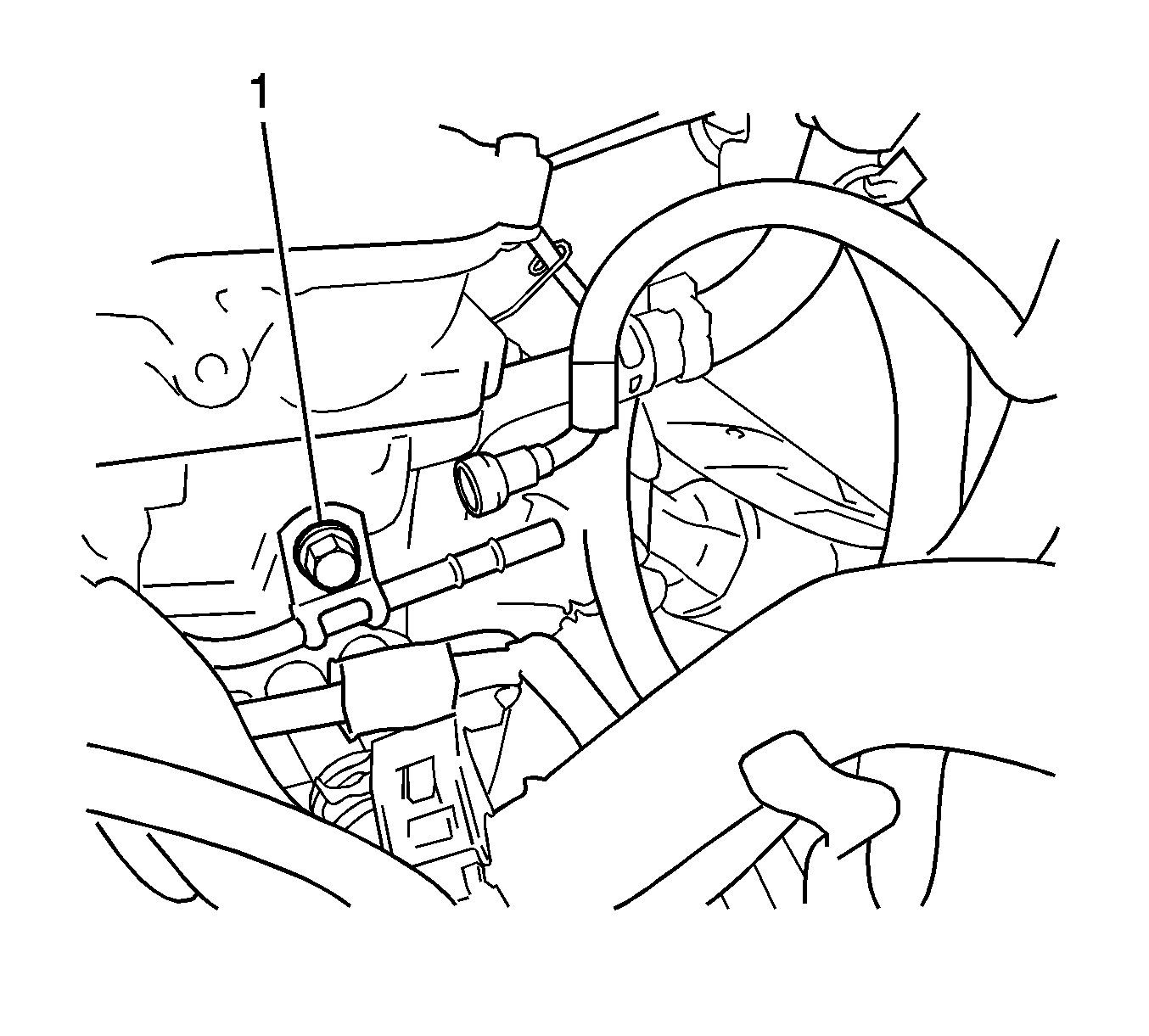
- Remove the fuel pipe clamp (1).
- Remove the fuel pipe clamp (2).
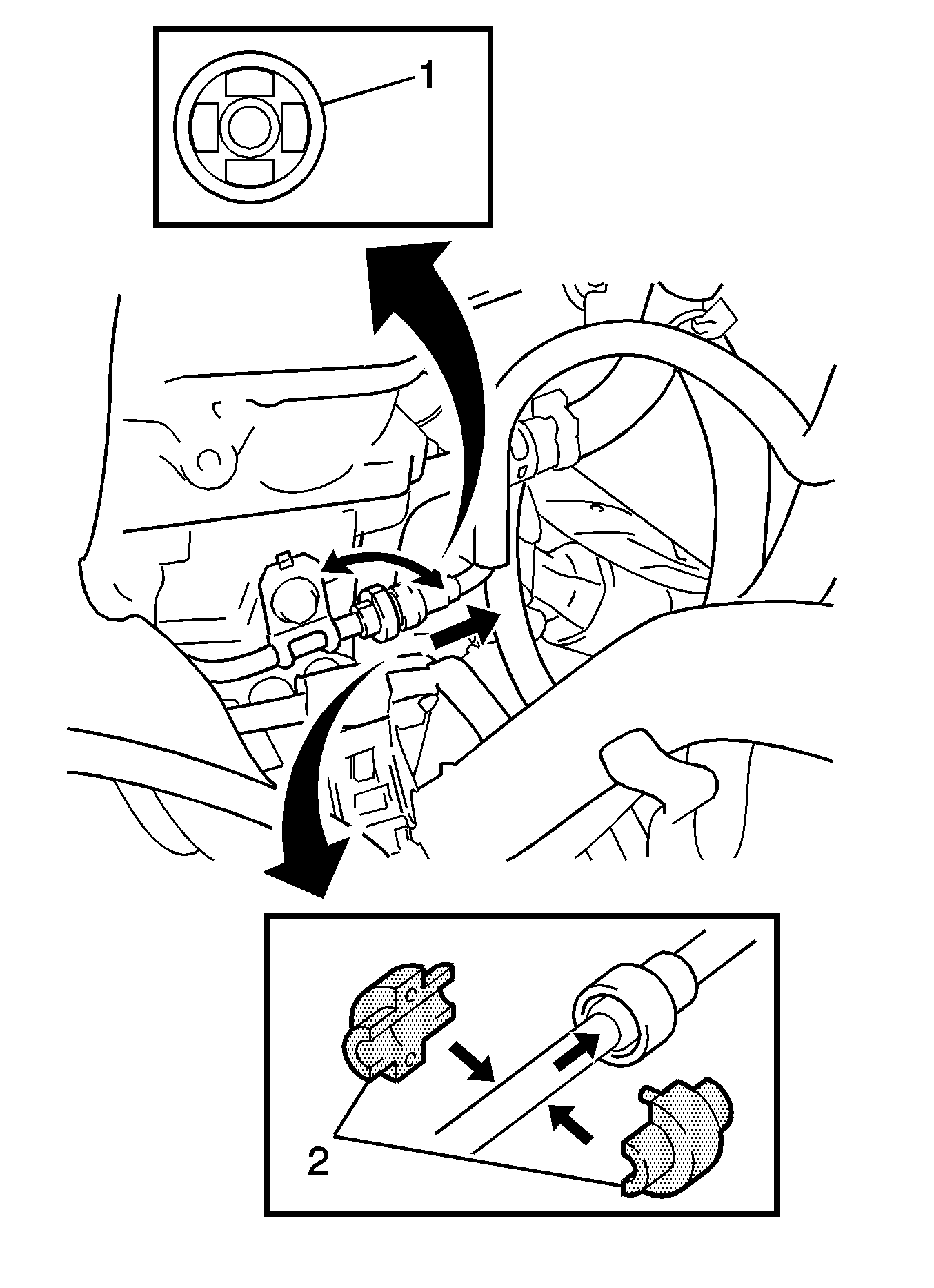
- Using the J-43178 disconnect tool , disconnect the fuel tube (1).
- Remove the fuel delivery pipe.
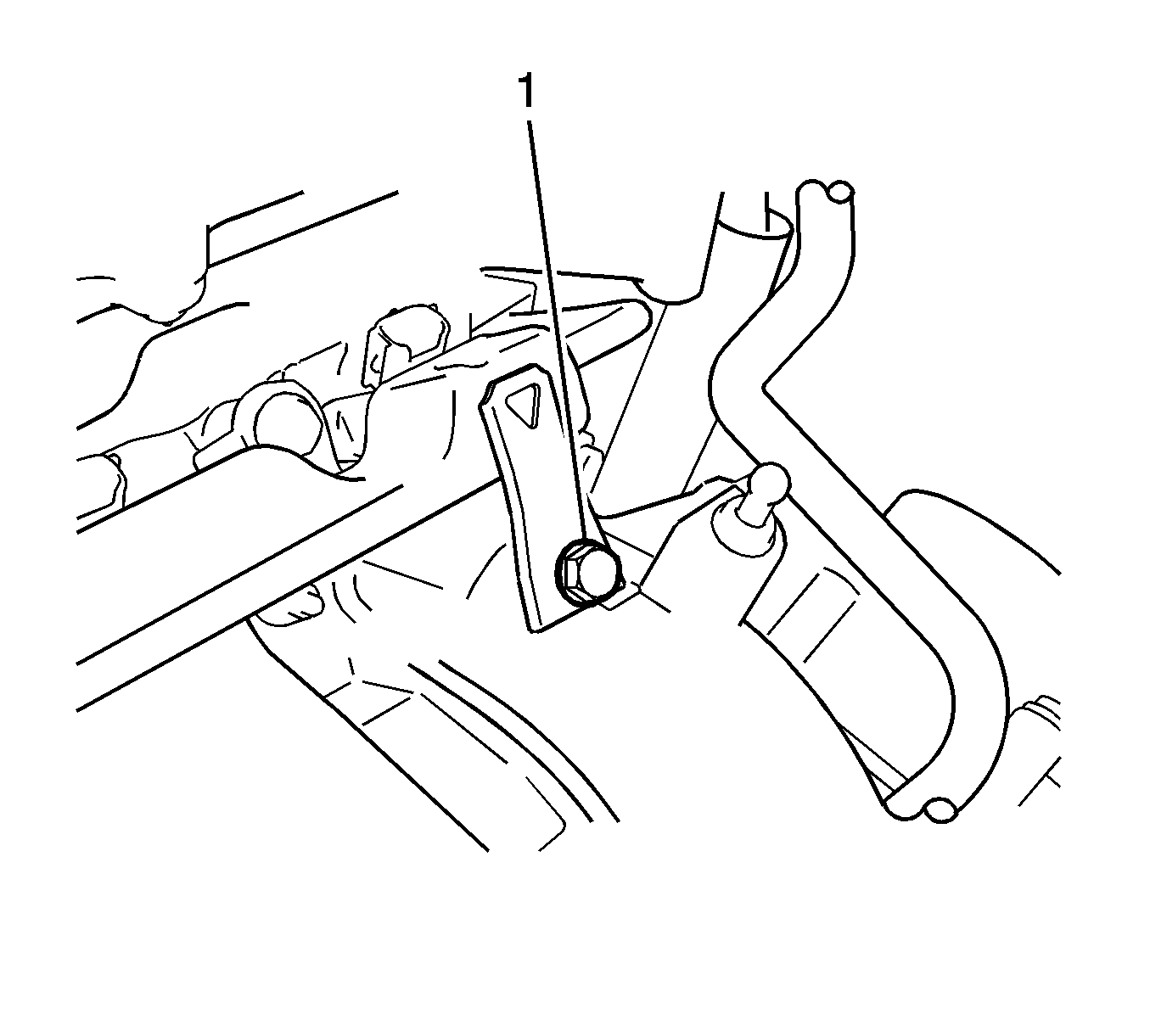
- Remove the bolt (1) and remove the wire harness bracket.
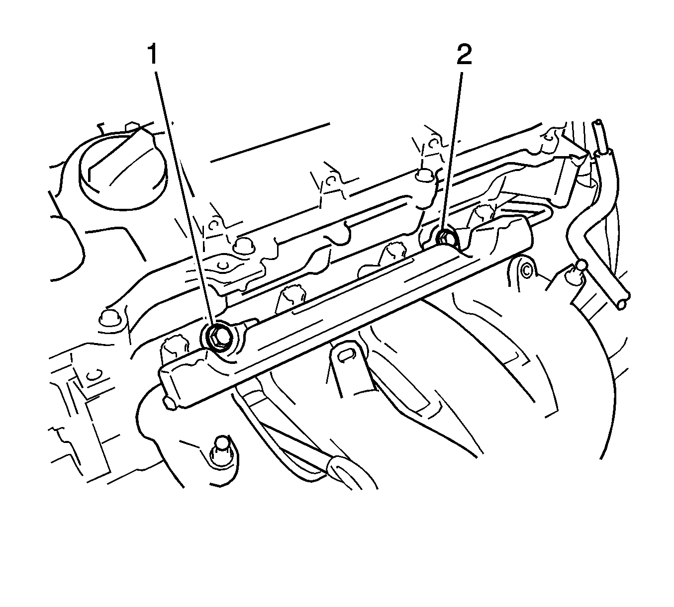
- Remove the 2 bolts (1, 2).
- Remove the bolt (1) and the fuel delivery pipe.
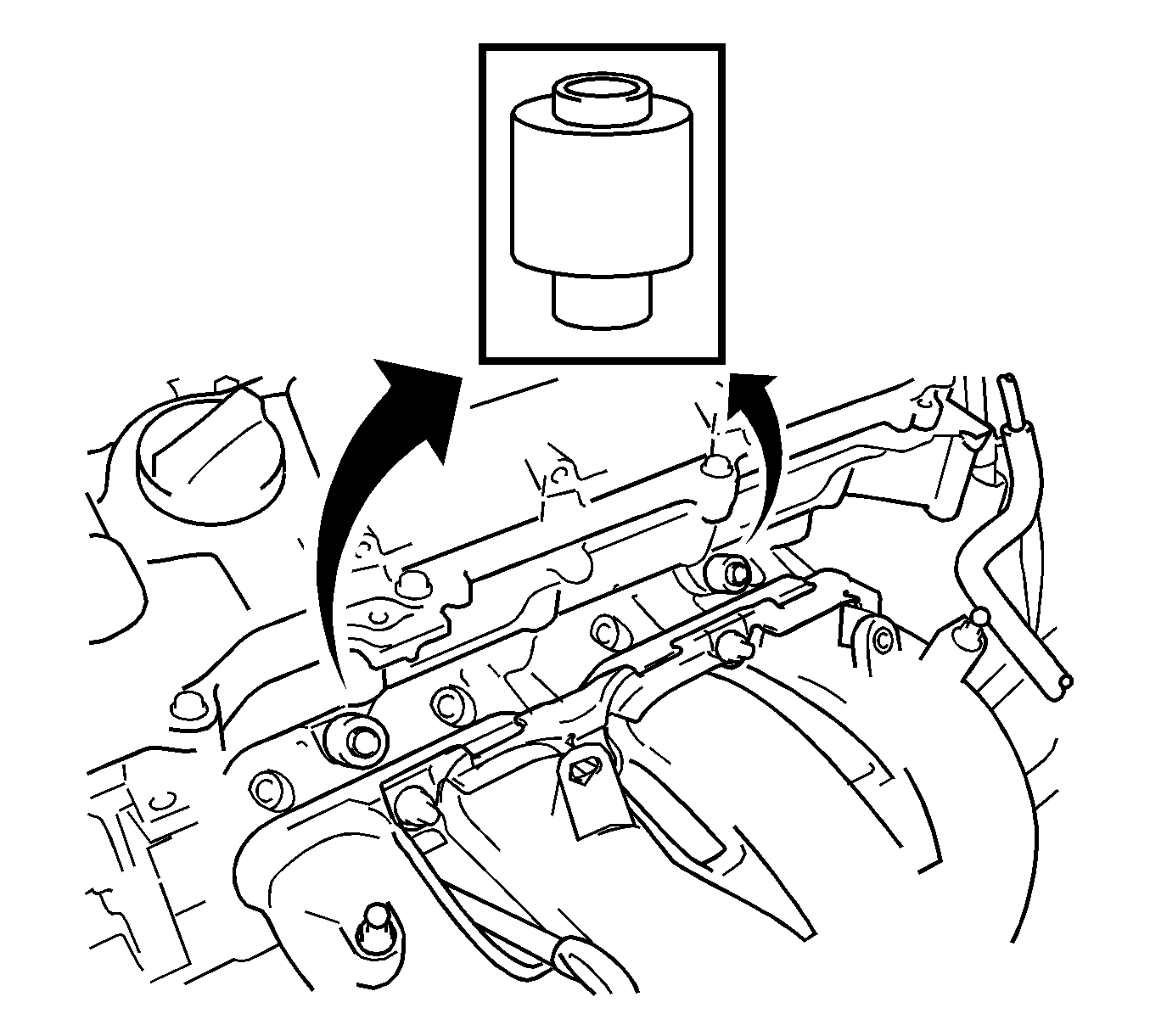
- Remove the 2 delivery pipe spacers.
- Pull the 4 fuel injector assemblies out of the fuel delivery pipe.
- For reinstallation, attach a tag or label to the injector shaft.
- Remove the 4 injector vibration insulators (1, 2, 3, 4).
Warning: Refer to Battery Disconnect Warning in the Preface section.
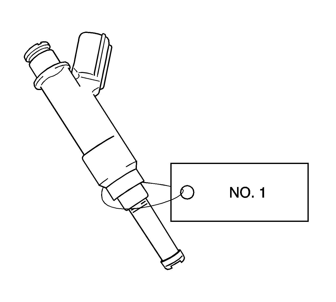
Note: Prevent entry of foreign objects by covering the fuel injector with a plastic bag.
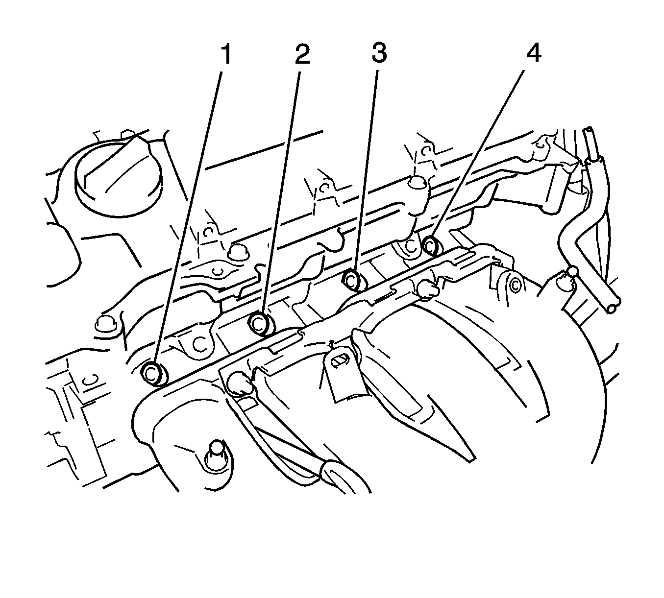
Installation Procedure
- Install a new injector vibration insulator (2) to the fuel injector assembly.
- Apply a light coat of oil to the contact surfaces of the O-ring (1) of the fuel injector assembly.
- While turning the fuel injector assembly left and right, install it onto the fuel delivery pipe.
- Install the 2 delivery pipe spacers onto the cylinder head.
- Install the fuel delivery pipe with the 4 fuel injector assemblies, then temporarily install the 2 bolts (1, 2).
- Install the 2 bolts and tighten to 21 N·m (15 lb ft).
- Install the bolt (1) to secure the fuel delivery pipe and tighten to 21 N·m (15 lb ft).
- Install the wire harness bracket with the bolt (1) and tighten to 5.0 N·m (44 lb in).
- Insert the fuel tube connector into the fuel delivery pipe (2) until a "click" sound can be heard.
- Install a new fuel pipe clamp (2).
- Install a new fuel pump clamp (1).
- Install the 2 wire harness brackets with the 2 bolts (1, 2) and tighten to 13 N·m (10 lb ft).
- Connect the 4 wire harness clamps (1, 2, 3, 4).
- Connect the 4 fuel injector assembly connectors (1, 2, 5, 6).
- Connect the 2 wire harness clamps (7, 8).
- Connect the ground wires with the 2 bolts (3, 4).
- Install the air cleaner assembly with hose.
- Connect the ventilation hose (1).
- Connect the cable to the negative battery terminal.
- Inspect for a fuel leak.
- Install the engine cover. Refer to Engine Cover Replacement.
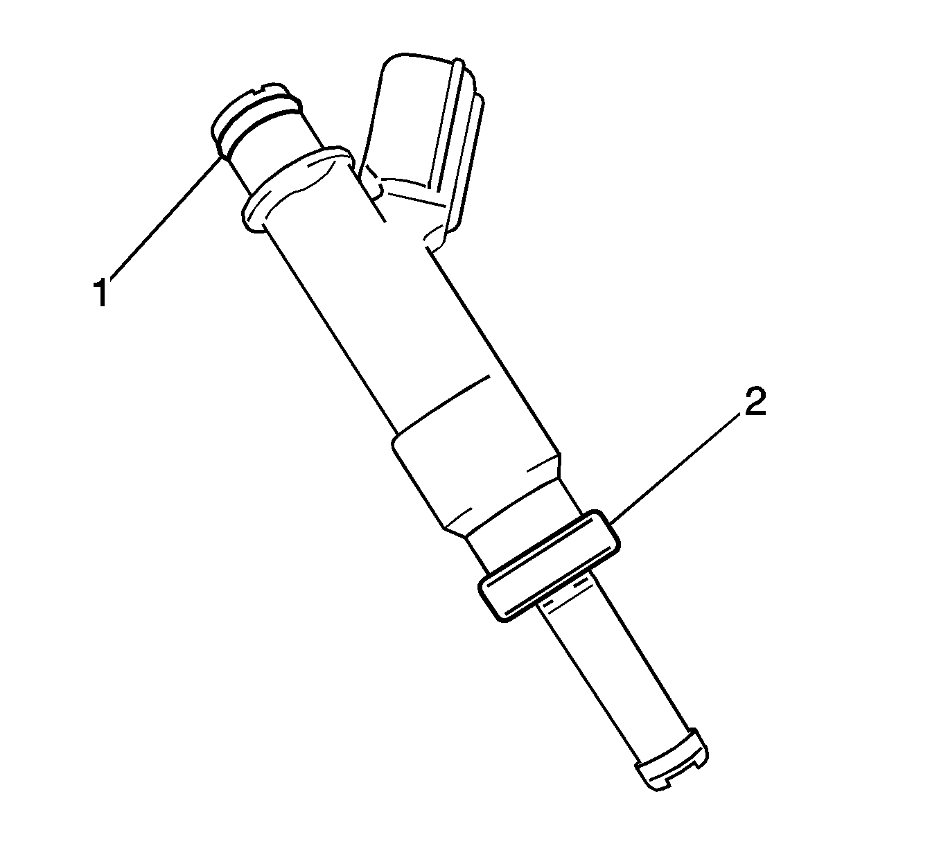
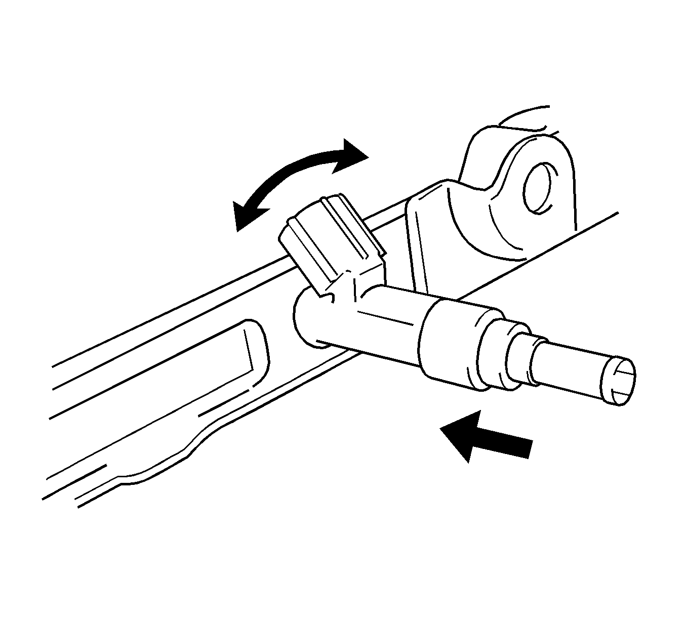
Note: Do not twist the O-ring. After installing the fuel injectors, check that they turn smoothly. If not, replace the O-ring with a new one.

Note: Install the delivery pipe spacers in the correct direction.

Caution: Refer to Fastener Caution in the Preface section.


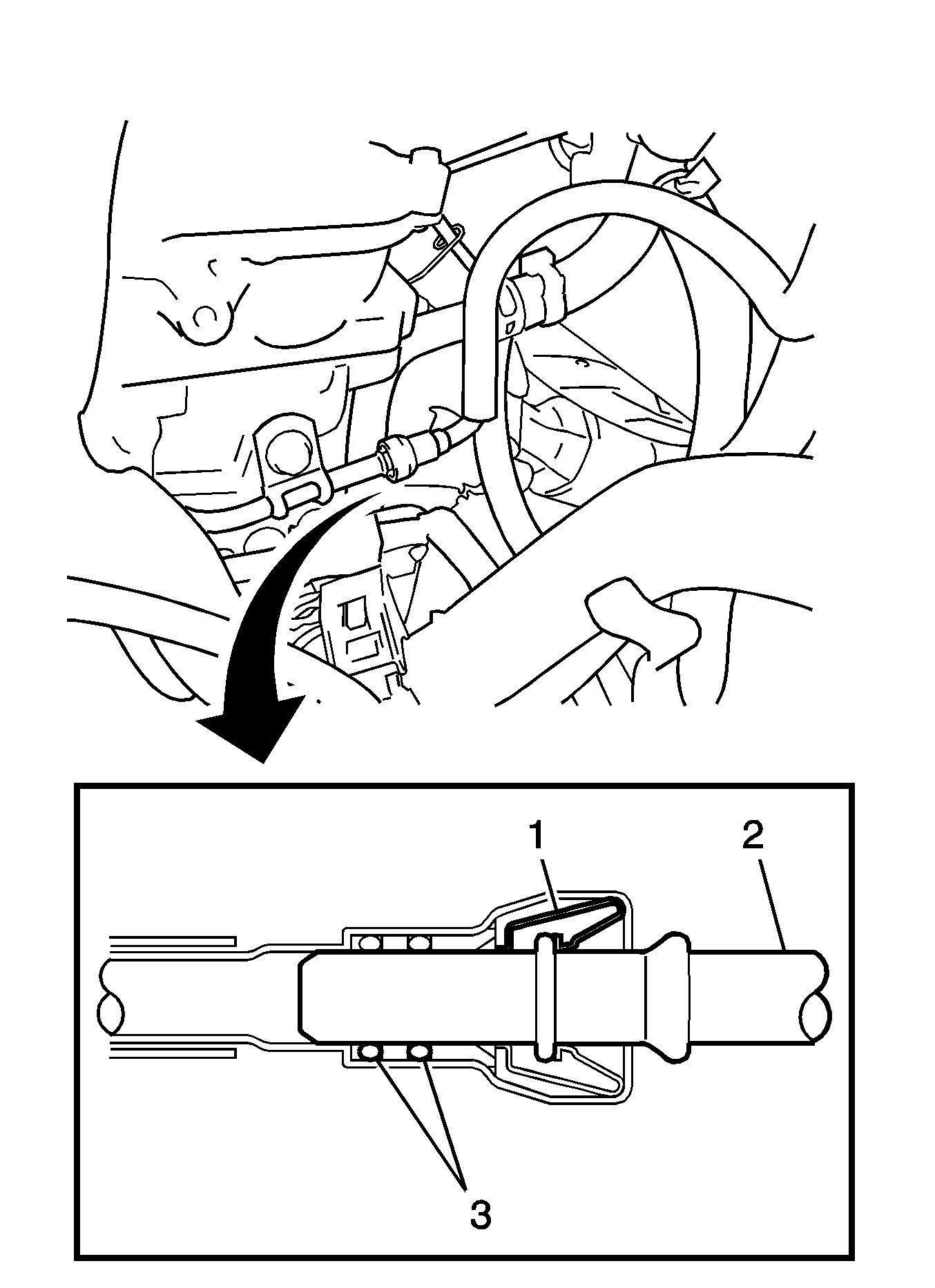
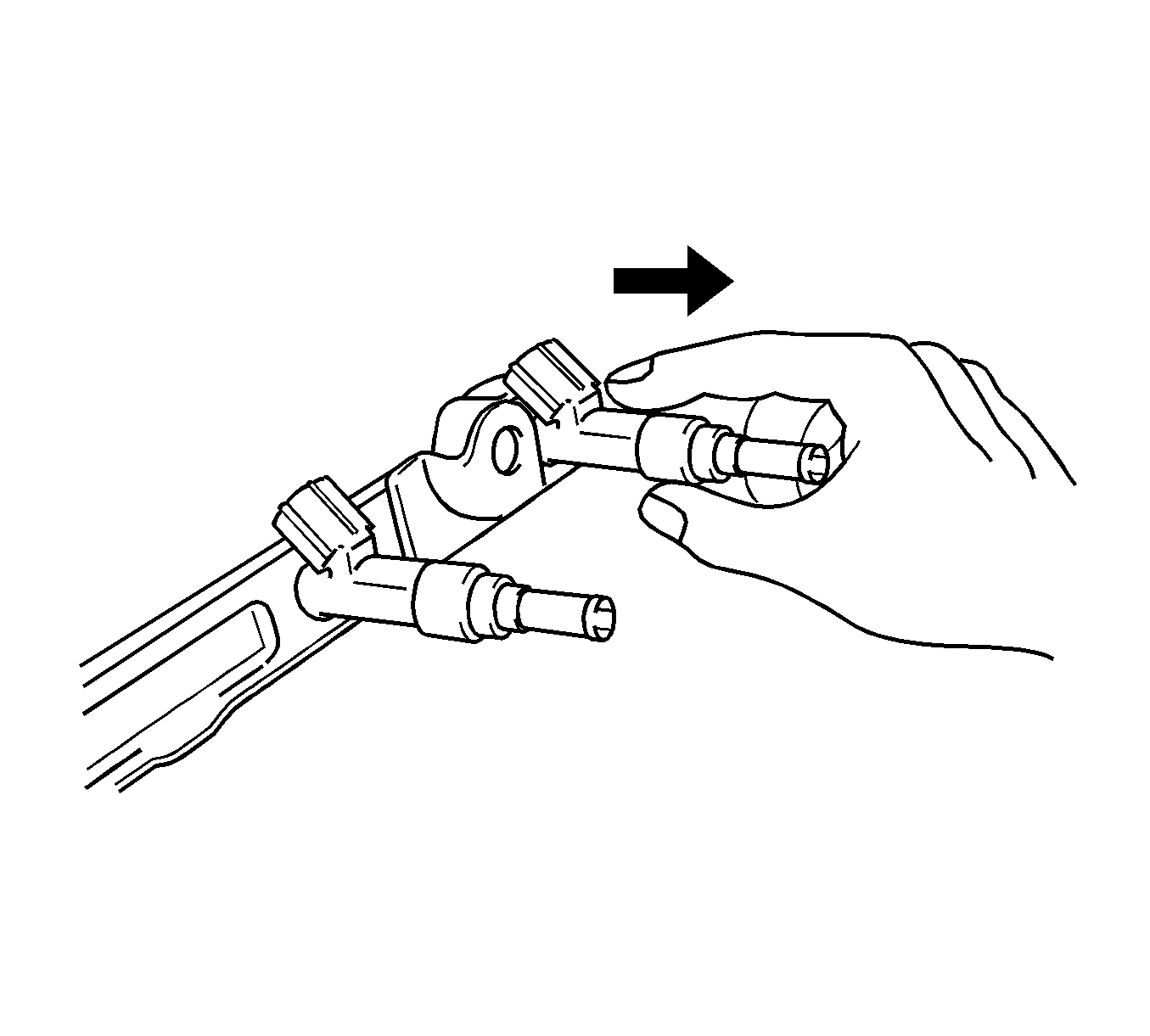
Note: Check that there are no scratches or foreign matter around the contact surfaces of the fuel tube connector and pipe before performing this work. After connecting the fuel tube, check that the fuel tube connector and pipe are securely connected by pulling on them.


Warning: Refer to Battery Disconnect Warning in the Preface section.
