Fuel Sender Assembly Replacement FWD
Removal Procedure
Caution: Gasoline or gasoline vapors are highly flammable. A fire could occur if an ignition source is present. Never drain or store gasoline or diesel fuel in an open container, due to the possibility of fire or explosion. Have a dry chemical (Class B) fire extinguisher nearby.
Caution: Provide proper ventilation when working with fuel in enclosed areas where fuel vapors can collect. The lack of adequate ventilation may result in personal injury.
Caution: Always wear safety goggles when working with fuel in order to protect the eyes from fuel splash.
Caution: Remove the rear compartment floor trim to provide technician contact with the vehicle's metal surfaces. Failure to remove the rear compartment floor trim may cause a static electricity discharge to ignite any fuel vapor resulting in personal injury and vehicle damage.
Caution: Fuel Vapors can collect while servicing fuel system parts in enclosed
areas such as a trunk. To reduce the risk of fire and increased exposure to
vapors:
• Use forced air ventilation such as a fan set outside
of the trunk. • Plug or cap any fuel system openings in order to reduce fuel vapor
formation. • Clean up any spilled fuel immediately. • Avoid sparks and any source of ignition. • Use signs to alert others in the work area that fuel system work
is in process.
Notice: Cap the fittings and plug the holes when servicing the fuel system in order to prevent dirt and other contaminants from entering the open pipes and passages.
Notice: Clean all of the following areas before performing any disconnections
in order to avoid possible contamination in the system:
• The fuel pipe connections • The hose connections • The areas surrounding the connections
Important:
• Always replace the fuel sender assembly O-rings when reinstalling the
fuel sender assembly. • Always maintain cleanliness when servicing fuel system components. • Do not bend the arm of the fuel gage float while removing the fuel sender
assembly.
- Relieve the fuel system pressure. Refer to Fuel Pressure Relief .
- Remove the two fasteners and swing the rear seat bottom cushion up and out of the way. Refer to Rear Seat Cushion Replacement in Seats.
- Remove the sill plate from the left side door opening.
- Fold back the carpet in order to maintain metal-to-metal contact while servicing the fuel sender assembly.
- Remove the access panel for the fuel sender assembly from the rear seat floor. The panel is held in place by a butyl caulk seal.
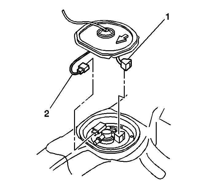
- Disconnect the fuel sender electrical connector (1) from the fuel sender assembly.
- Disconnect the electrical connector of the fuel tank pressure (FTP) sensor (2) from the fuel sender assembly.
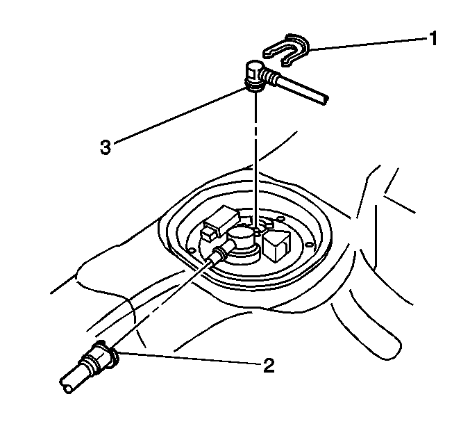
- Remove the retaining clip (1) from the fuel line fitting.
- Remove the fuel line (3) from the fuel sender assembly.
- Disconnect the fuel tank vapor line (2) from the fuel sender assembly.
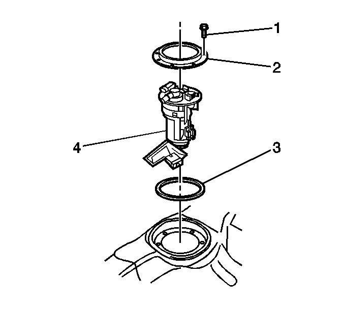
- Remove the 8 bolts (1) retaining the hold down plate (2) for the fuel sender assembly.
- Remove the hold down plate (2).
- Clean the fuel pipe and the fuel sender assembly to prevent possible fuel contamination during removal.
- Remove the fuel sender assembly (4) from the fuel tank.
- Inspect and clean O-ring sealing surfaces on the fuel sender assembly .
Installation Procedure
Notice: Always re-attach the fuel lines and fuel filter with all original type fasteners and hardware.
Do not repair sections of fuel pipes.- Position the new fuel sender assembly O-ring (3) on the fuel sender assembly.
- Install the fuel sender assembly (4) into the fuel tank.
- Install the hold down plate (2) for the fuel sender assembly .
- Secure the hold down plate for the fuel sender assembly with the 8 bolts (1).
- Install the fuel tank vapor line (2) to the fuel sender fitting.
- Install the fuel pipe (3) to the fuel sender fitting.
- Secure the fuel pipe (3) with the retaining clip (1).
- Connect the fuel sender electrical connector (1) to the fuel sender assembly.
- Connect the FTP sensor electrical connector (2) to the fuel sender assembly.
- Connect the negative battery cable.
- Pressurize the fuel system and check for leaks.
- Inspect the butyl caulk seal for the fuel sender access panel. Replace any missing butyl caulk as necessary.
- Install the access panel to the rear seat floor.
- Relocate the carpet under the seat and the left sill plate area.
- Install the sill plate to the left side door opening .
- Install the rear seat bottom cushion.
- Secure the seat cushion with the two fasteners. Refer to Rear Seat Cushion Replacement in Seats.

Notice: Use the correct fastener in the correct location. Replacement fasteners must be the correct part number for that application. Fasteners requiring replacement or fasteners requiring the use of thread locking compound or sealant are identified in the service procedure. Do not use paints, lubricants, or corrosion inhibitors on fasteners or fastener joint surfaces unless specified. These coatings affect fastener torque and joint clamping force and may damage the fastener. Use the correct tightening sequence and specifications when installing fasteners in order to avoid damage to parts and systems.
Tighten
Tighten the bolts to 6 N·m (53 lb in).


Fuel Sender Assembly Replacement AWD
Removal Procedure
Caution: Gasoline or gasoline vapors are highly flammable. A fire could occur if an ignition source is present. Never drain or store gasoline or diesel fuel in an open container, due to the possibility of fire or explosion. Have a dry chemical (Class B) fire extinguisher nearby.
Caution: Provide proper ventilation when working with fuel in enclosed areas where fuel vapors can collect. The lack of adequate ventilation may result in personal injury.
Caution: Always wear safety goggles when working with fuel in order to protect the eyes from fuel splash.
Caution: Remove the rear compartment floor trim to provide technician contact with the vehicle's metal surfaces. Failure to remove the rear compartment floor trim may cause a static electricity discharge to ignite any fuel vapor resulting in personal injury and vehicle damage.
Caution: Fuel Vapors can collect while servicing fuel system parts in enclosed
areas such as a trunk. To reduce the risk of fire and increased exposure to
vapors:
• Use forced air ventilation such as a fan set outside
of the trunk. • Plug or cap any fuel system openings in order to reduce fuel vapor
formation. • Clean up any spilled fuel immediately. • Avoid sparks and any source of ignition. • Use signs to alert others in the work area that fuel system work
is in process.
Notice: Cap the fittings and plug the holes when servicing the fuel system in order to prevent dirt and other contaminants from entering the open pipes and passages.
Notice: Clean all of the following areas before performing any disconnections
in order to avoid possible contamination in the system:
• The fuel pipe connections • The hose connections • The areas surrounding the connections
Important:
• Always replace the fuel sender assembly O-rings when reinstalling the
fuel sender assembly. • Always maintain cleanliness when servicing fuel system components. • Do not bend the arm of the fuel gage float while removing the fuel sender
assembly.
- Relieve the fuel system pressure. Refer to Fuel Pressure Relief .
- Remove the two fasteners and swing the rear seat bottom cushion up and out of the way. Refer to Rear Seat Cushion Replacement in Seats.
- Remove the sill plate from the left side door opening .
- Fold back the carpet in order to maintain metal-to-metal contact while servicing the fuel sender assembly.
- Remove the access panel for the fuel sender assembly from the rear seat floor. The panel is held in place by a butyl caulk seal.
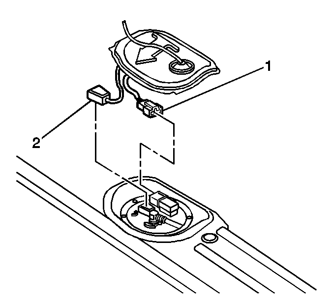
- Disconnect the fuel sender electrical connector (2) from the fuel sender assembly .
- Disconnect the FTP sensor electrical connector (1) from the fuel sender assembly .
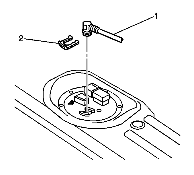
- Remove the retaining clip (2) from the fuel line fitting .
- Remove the fuel line (1) from the fuel sender assembly.
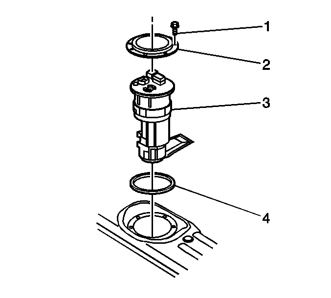
- Remove the 8 bolts (1) retaining the hold down plate (2) for the fuel sender assembly.
- Remove the hold down plate (2).
- Clean the fuel pipe and the fuel sender assembly to prevent possible fuel contamination during removal.
- Remove the fuel sender assembly (3) from the fuel tank.
- Inspect and clean O-ring sealing surfaces on the fuel sender assembly .
Installation Procedure
Notice: Always re-attach the fuel lines and fuel filter with all original type fasteners and hardware.
Do not repair sections of fuel pipes.- Position the new fuel sender assembly O-ring (4) on the fuel sender assembly.
- Install the fuel sender assembly (3) into the fuel tank.
- Install the hold down plate (2) for the fuel sender assembly .
- Secure the hold down plate for the fuel sender assembly with the 8 bolts (1).
- Install the fuel pipe (1) to the fuel sender fitting.
- Secure the fuel pipe (1) with the retaining clip (2).
- Connect the fuel sender electrical connector (2) to the fuel sender assembly.
- Connect the FTP sensor electrical connector (1) to the fuel sender assembly.
- Connect the negative battery cable.
- Pressurize the fuel system and check for leaks.
- Inspect the butyl caulk seal for the fuel sender access panel. Replace any missing butyl caulk as necessary.
- Install the access panel to the rear seat floor.
- Relocate the carpet under the seat and the left sill plate area.
- Install the sill plate to the left side door opening .
- Install the rear seat bottom cushion.
- Secure the seat cushion with the two fasteners. Refer to Rear Seat Cushion Replacement in Seats.

Notice: Use the correct fastener in the correct location. Replacement fasteners must be the correct part number for that application. Fasteners requiring replacement or fasteners requiring the use of thread locking compound or sealant are identified in the service procedure. Do not use paints, lubricants, or corrosion inhibitors on fasteners or fastener joint surfaces unless specified. These coatings affect fastener torque and joint clamping force and may damage the fastener. Use the correct tightening sequence and specifications when installing fasteners in order to avoid damage to parts and systems.
Tighten
Tighten the bolts to 6 N·m (53 lb in).


