For 1990-2009 cars only
Upper Control Arm Replacement AWD
Removal Procedure
- Remove the rear drive module. Refer to Crossmember Replacement .
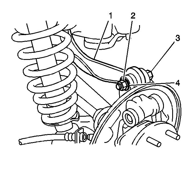
- Use paint in order to place match marks on the camber adjust cams and on the upper control arm (1).
- Remove the nut (2) and the bolt (3) in order to separate the upper control arm from the knuckle.
- Remove the nut from the cam bolt.
- Remove the rear cam from the cam bolt.
- Remove the cam bolt and the upper control arm from the crossmember.
Installation Procedure
- If you are replacing the upper control arm (1), copy the match marks from the old components to the new components.
- Align the match marks and install the upper control arm and the cam bolt to the rear suspension crossmember.
- Align the match marks and install the cam and the nut to the cam bolt.
- Install the nut (2) and the bolt (3) in order to retain the upper control arm to the knuckle.
- Install the rear drive module. Refer to Crossmember Replacement .
- With the weight of the vehicle on the tire and wheel assemblies, tighten the 2 nuts and the 2 bolts.
- Measure the wheel alignment. Adjust if necessary. Refer to Wheel Alignment Measurement in Wheel Alignment.
Important: Do not tighten the nuts or the bolts. The weight of the vehicle must be on the tire and wheel assemblies before tightening the nuts and the bolts.
Notice: Refer to Fastener Notice in the Preface section.
Tighten
Tighten the nuts and the bolts to 74 N·m (54.6 lb ft).
