For 1990-2009 cars only
Knuckle Replacement AWD
Removal Procedure
- Apply the park brake.
- Raise and support the vehicle. Refer to Lifting and Jacking the Vehicle in General Information.
- Remove the rear tire and wheel assembly. Refer to Tire and Wheel Removal and Installation in Tires and Wheels.
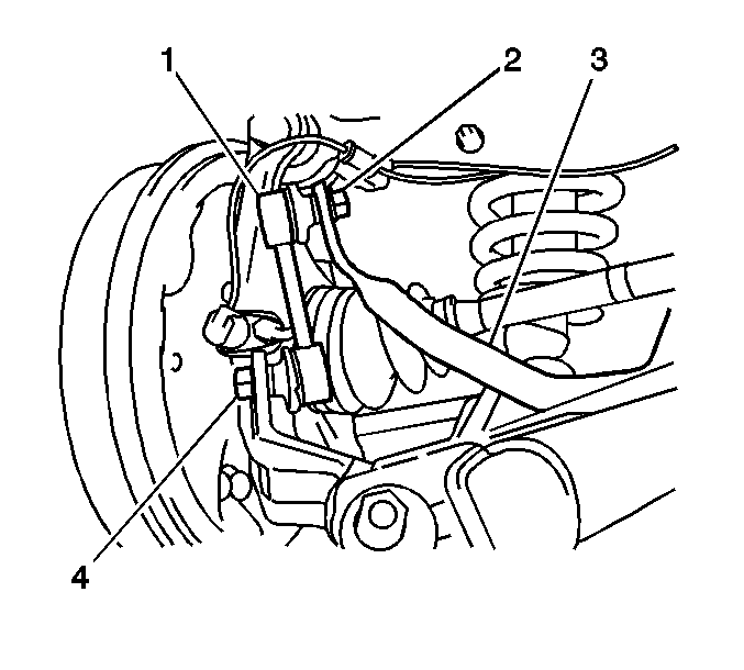
- Remove the nut (4) in order to separate the stabilizer shaft link stud from the knuckle.
- Remove and discard the cotter pin from the wheel drive shaft nut.
- Remove the lock cap from the wheel drive shaft nut.
- Remove and discard the wheel drive shaft nut.
- Release the park brake.
- If the vehicle has ABS, remove the rear wheel speed sensor and pigtail. Refer to Rear Wheel Speed Sensor Replacement in ABS.
- Remove the brake drum. Refer to Brake Drum Replacement in Drum Brakes.
- Remove the brake shoes and the brake hardware. Refer to Brake Shoe Replacement in Drum Brakes.
- Use containers in order to catch the brake fluid.
- Remove the wheel cylinder. Refer to Wheel Cylinder Replacement .
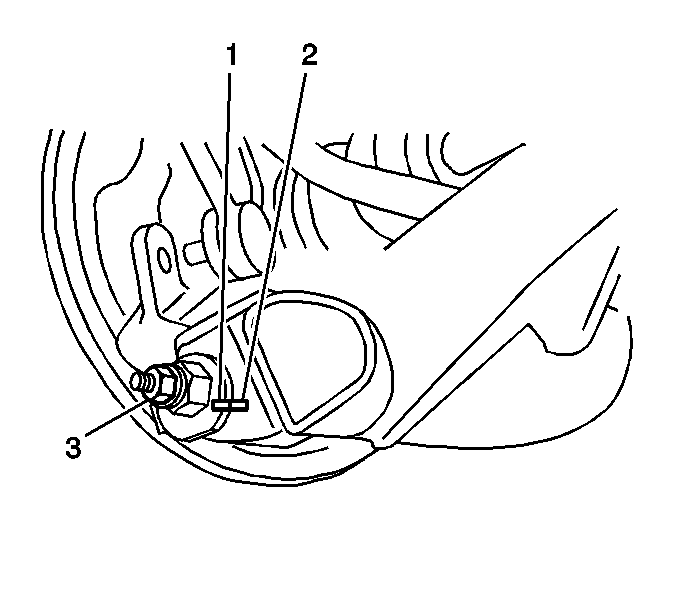
- Use paint in order to place match marks (1,2) on the camber adjust cams.
- Remove the nut (3) and the cam.
- Remove the cam bolt.
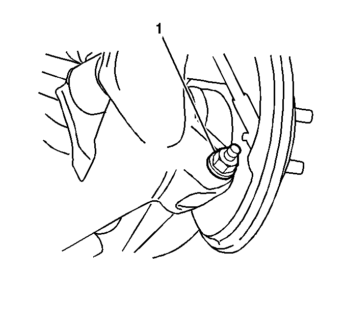
- Remove the nut (1) and the bolt in order to separate the lower control arm from the knuckle.
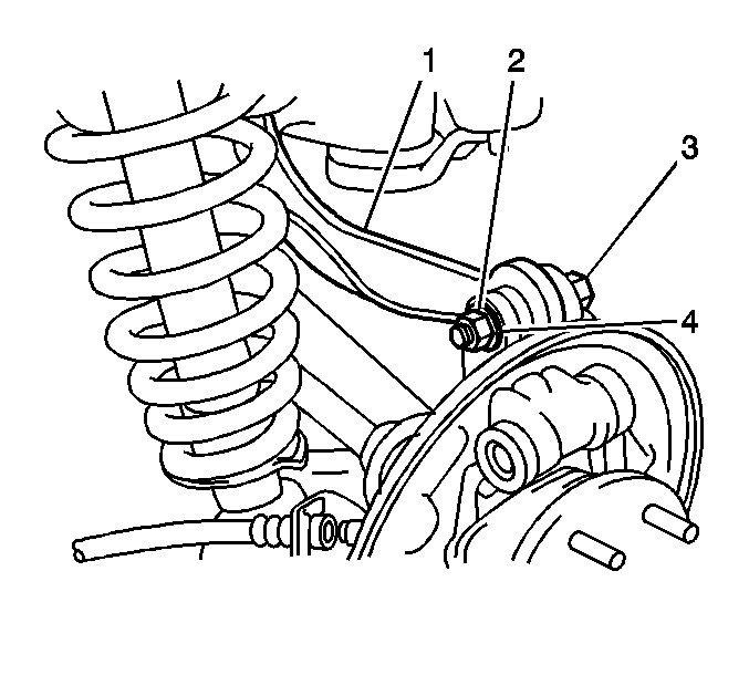
- Remove the nut (2) and the bolt (3) in order to separate the upper control arm (1) from the knuckle.
- Remove the knuckle from the wheel drive shaft.
- Remove the wheel bearing and hub assembly. Refer to Rear Wheel Bearing and Hub Replacement .
- Remove the drum brake backing plate.


Important: Support the wheel drive shaft.
Installation Procedure
- Install the drum brake backing plate and the wheel bearing and hub assembly to the knuckle. Refer to Rear Wheel Bearing and Hub Replacement .
- Install the knuckle to the wheel drive shaft.
- Install the bolt (3) and the nut (2) in order to retain the knuckle to the upper control arm (1).
- Install the bolt and the nut (1) to the front of the rear lower control arm.
- Align the match marks (1,2) and install the cam bolt to the rear of the rear lower control arm.
- Align the match marks and install the cam to the cam bolt.
- Install the nut (3) to the cam bolt.
- Install the wheel cylinder. Refer to Wheel Cylinder Replacement .
- Install the brake shoes and the brake hardware. Refer to Brake Shoe Replacement in Drum Brakes.
- Install the brake drum. Refer to Brake Drum Replacement in Drum Brakes.
- Apply the park brake.
- Install a NEW wheel drive shaft spindle nut.
- Slowly tighten the nut in order to draw the wheel drive shaft spindle into the wheel bearing and hub.
- Install the lock cap.
- Install a NEW cotter pin.
- If the vehicle has ABS, install the rear wheel speed sensor and pigtail. Refer to Rear Wheel Speed Sensor Replacement in ABS.
- Install the nut (4) in order to retain the stabilizer shaft link stud to the knuckle.
- Install the rear tire and wheel assembly. Refer to Tire and Wheel Removal and Installation in Tires and Wheels.
- Lower the vehicle.
- Bounce the rear of the vehicle in order to stabilize the suspension.
- Tighten the nut and the bolt that retains the upper control arm to the knuckle.
- Align the match marks and tighten the nut and the cam bolt that retains the rear of the lower control arm to the knuckle.
- Tighten the nut and the bolt that retains the front of the lower control arm to the knuckle.
- Release the park brake.
- Bleed the brake system. Refer to Hydraulic Brake System Bleeding in Hydraulic Brakes.
- Measure the wheel alignment. Adjust if necessary. Refer to Wheel Alignment Measurement in Wheel Alignment.

Important: Do not tighten the nuts or the bolts on the control arms. The weight of the vehicle must be on the tire and wheel assemblies before tightening the nuts and the bolts.


Notice: Refer to Fastener Notice in the Preface section.
Tighten
Tighten the nut to 216 N·m (159.3 lb ft).

Tighten
Tighten the nut to 44 N·m (32.5 lb ft).
Important: The weight of the vehicle must be on the tire and wheel assemblies.
Tighten
Tighten the nut and the bolt to 74 N·m (54.6 lb ft).
Tighten
Tighten the nut and the bolt to 74 N·m (54.6 lb ft).
Tighten
Tighten the nut and the bolt to 74 N·m (54.6 lb ft).
