For 1990-2009 cars only
Removal Procedure
- Remove the timing chain. Refer to Timing Chain and Sprocket Replacement .
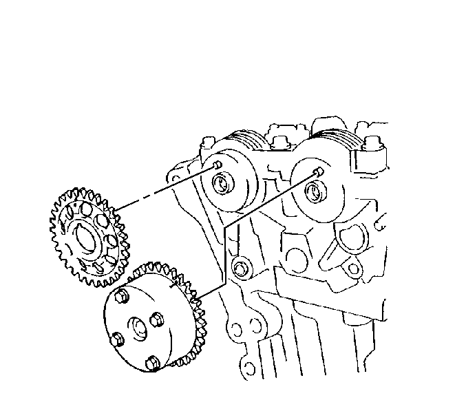
- Remove the camshaft position actuator from the camshaft.
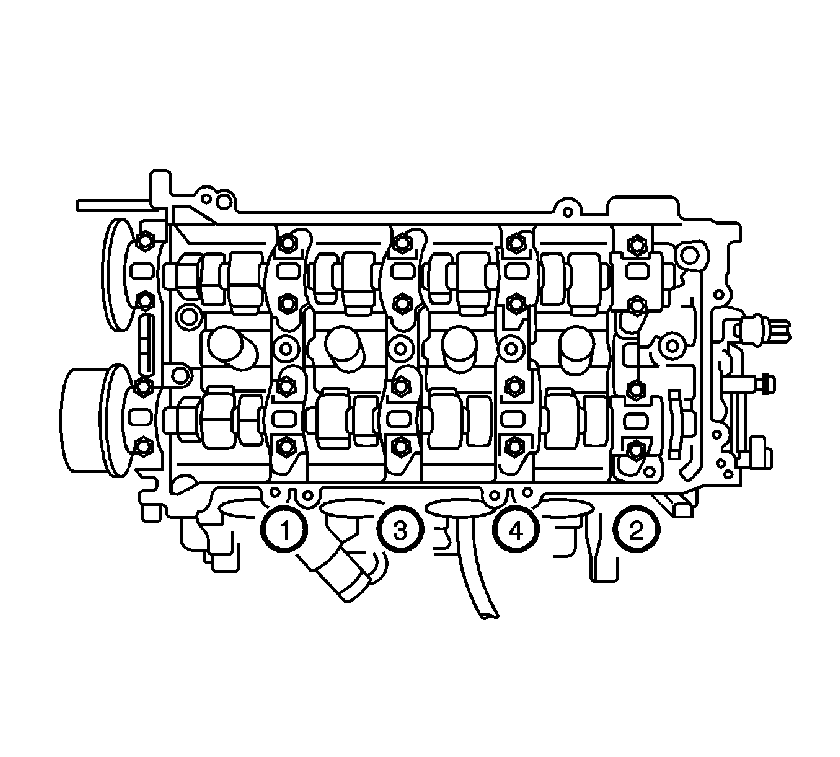
- Remove the intake camshaft bearing cap bolts in sequence. Starting at the ends and working toward the center of the camshaft.
- Remove the front camshaft bearing cap.
- Remove the intake camshaft from the cylinder head.
Important: When performing any service procedure that pertains to the camshaft or the camshaft actuator, unlock the camshaft actuator locking pin. Refer to Camshaft Actuator Locking Pin Adjustment .


Installation Procedure
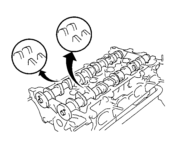
- Install the intake camshaft onto the cylinder head with the number 1 cam lobes facing as shown.
- Install the camshaft bearing caps in the proper locations and direction.
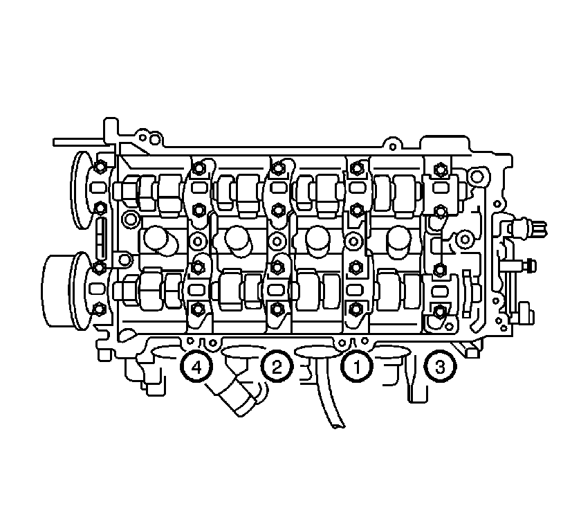
- Install the camshaft bearing cap bolts.
- Install the front camshaft bearing cap.
- Install the camshaft position actuator to the camshaft.
- Install the camshaft position actuator sprocket bolt in order to secure the cam sprocket.
- Install the timing chain. Refer to Timing Chain and Sprocket Replacement .
- Unlock the camshaft actuator locking pin. Refer to Camshaft Actuator Locking Pin Adjustment .
- Check and adjust valve clearance. Refer to Valve Lash Adjustment .

Important: Each bearing cap has a number and a directional arrow marked on the bearing cap.
Notice: Refer to Fastener Notice in the Preface section.

Tighten
Tighten the bolts in the sequence shown to 19 N·m (14 lb ft).
Tighten
Tighten the bearing cap bolts to 19 N·m (14 lb ft).

Tighten
Tighten the bolt to 54 N·m (40 lb ft).
