Removal Procedure
- Raise and support the vehicle. Refer to Lifting and Jacking the Vehicle in General Information.
- Remove the 2 rear tire and wheel assemblies. Refer to Tire and Wheel Removal and Installation in Tires and Wheels.
- Remove the catalytic converter. Refer to Catalytic Converter Replacement in Engine Exhaust.
- Remove the propeller shaft. Refer to Two-Piece Propeller Shaft Replacement in Propeller Shaft.
- Remove the left rear park brake cable from the equalizer. Refer to Parking Brake Rear Cable Replacement - Left Side in Park Brake.
- Remove the right rear park brake cable from the equalizer. Refer to Parking Brake Rear Cable Replacement - Right Side in Park Brake.
- If the vehicle has ABS, remove the 2 rear wheel speed sensors and pigtails. Refer to Rear Wheel Speed Sensor Replacement in Antilock Brake System.
- Use containers in order to catch the brake fluid.
- Remove the brake pipe from the left wheel cylinder.
- Remove the brake pipe from the right wheel cylinder.
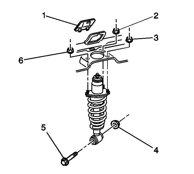
- Remove the nut (4) and the bolt (5) in order to separate the left rear shock absorber from the lower control arm.
- Remove the nut and the bolt in order to separate the right rear shock absorber from the lower control arm.
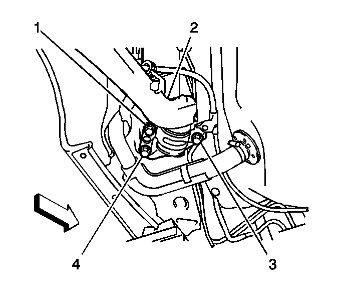
- Remove the 3 bolts (1, 3, 4) in order to separate the front of the left rear lower control arm (2) from the body.
- Remove the 3 bolts in order to separate the front of the right rear lower control arm from the body.
- Place a jack under the differential support.
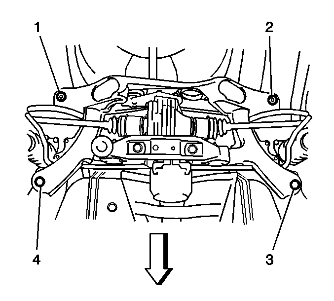
- Remove the 2 bolts (3, 4) and the 2 nuts (1, 2) in order to separate the rear suspension crossmember and the rear drive module from the body.
- Lower the rear drive module.
- Remove the stabilizer shaft links. Refer to Stabilizer Shaft Link Replacement in Rear Suspension.
- Remove the stabilizer shaft. Refer to Stabilizer Shaft Replacement in Rear Suspension.
- Remove the brake drums. Refer to Brake Drum Replacement in Drum Brakes.
- Remove the brake shoes and the brake hardware. Refer to Brake Shoe Replacement in Drum Brakes.
- Remove the park brake cables. Refer to Parking Brake Rear Cable Replacement - Left Side and Parking Brake Rear Cable Replacement - Right Side in Park Brake.
- Remove the backing plates and the knuckles. Refer to Knuckle Replacement in Rear Suspension.
- Remove the rear wheel drive shafts. Refer to Rear Wheel Drive Shaft Replacement in Wheel Drive Shafts.
- Remove the upper control arms. Refer to Upper Control Arm Replacement in Rear Suspension.
- Remove the lower control arms. Refer to Lower Control Arm Replacement in Rear Suspension.
- Remove the differential carrier and the support. Refer to Differential Carrier Assembly Replacement in Rear Drive Axle.
Important: If you are removing the rear suspension crossmember
in order to gain access to other components, you may remove the following components
together as a rear drive module:
• The rear suspension crossmember • The differential carrier • The differential support • The rear wheel drive shafts • The upper control arms • The lower control arms • The stabilizer shaft • The knuckles • The drum brakes • The rear park brake cables
Important: If you are replacing components on the rear drive module, continue with this procedure.
Installation Procedure
- If you are replacing a control arm, copy the match marks from the old components to the new components.
- Install the differential carrier and the support to the crossmember. Refer to Differential Carrier Assembly Replacement in Rear Drive Axle.
- Install the nut (1) and the bolt (3) in order to retain the left rear lower control arm to the crossmember.
- Install the nut and the bolt in order to retain the right rear lower control arm to the crossmember.
- Align the match marks and install the cam and the cam bolt and the left rear upper control arm to the crossmember.
- Install the nut to the cam bolt on the left rear upper control arm.
- Align the match marks and install the cam and the cam bolt and the right rear upper control arm to the crossmember.
- Install the nut to the cam bolt on the right rear upper control arm.
- Install the rear wheel drive shafts. Refer to Rear Wheel Drive Shaft Replacement in Wheel Drive Shafts.
- Install backing plates and the knuckles. Refer to Knuckle Replacement in Rear Suspension.
- Install the left rear park brake cable to the backing plate. Refer to Parking Brake Rear Cable Replacement - Left Side in Park Brake.
- Install the right rear park brake cable to the backing plate. Refer to Parking Brake Rear Cable Replacement - Right Side in Park Brake.
- Install the brake shoes and the brake hardware. Refer to Brake Shoe Replacement in Drum Brakes.
- Install the brake drums. Refer to Brake Drum Replacement in Drum Brakes.
- Install the stabilizer shaft. Refer to Stabilizer Shaft Replacement in Rear Suspension.
- Install the stabilizer shaft links. Refer to Stabilizer Shaft Link Replacement in Rear Suspension.
- Use a jack in order to raise the rear drive module.
- Install the 2 nuts (1, 2) and the 2 bolts (3, 4) in order to retain the crossmember and the rear drive module to the body.
- Install the 3 bolts (1, 3, 4) in order to retain the front of the left rear lower control arm (2) to the body.
- Install the 3 bolts in order to retain the front of the right rear lower control arm to the body.
- Install the nut and the bolt in order to retain the left rear shock absorber to the lower control arm.
- Install the nut and the bolt in order to retain the right rear shock absorber to the lower control arm.
- Install the brake pipe to the left wheel cylinder.
- Install the brake pipe to the right wheel cylinder.
- If the vehicle has ABS, install the 2 rear wheel speed sensors and pigtails. Refer to Rear Wheel Speed Sensor Replacement in Antilock Brake System.
- Install the left rear park brake cable to the equalizer. Refer to Parking Brake Rear Cable Replacement - Left Side in Park Brake.
- Install the right rear park brake cable to the equalizer. Refer to Parking Brake Rear Cable Replacement - Right Side in Park Brake.
- Install the propeller shaft. Refer to Two-Piece Propeller Shaft Replacement in Propeller Shaft.
- Install the catalytic converter. Refer to Catalytic Converter Replacement in Engine Exhaust.
- Install the 2 rear tire and wheel assemblies. Refer to Tire and Wheel Removal and Installation in Tires and Wheels.
- Lower the vehicle.
- Bounce the rear of the vehicle in order to stabilize the suspension.
- Install the nut and the bolt that retains the left rear upper control arm to the knuckle.
- Install the nut and the bolt that retains the right rear upper control arm to the knuckle.
- Align the match marks and tighten the nut and the cam bolt that retains the left rear upper control arm to the crossmember.
- Align the match marks and tighten the nut and the cam bolt that retains the right rear upper control arm to the crossmember.
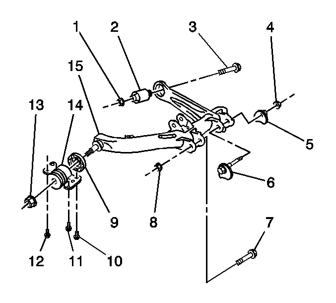
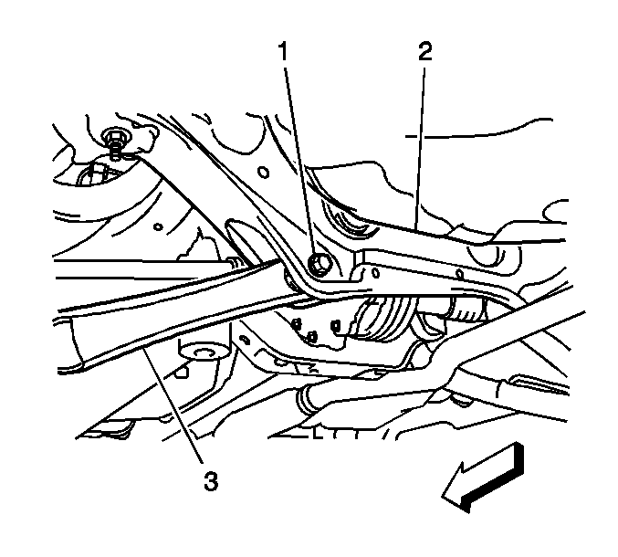
- Install the nut and the bolt (1) that retains the left rear lower control arm to the crossmember (2).
- Install the nut and the bolt that retains the right rear lower control arm to the crossmember.
- Install the nut and the bolt on that retains the left rear shock absorber to the lower control arm.
- Install the nut and the bolt on that retains the right rear shock absorber to the lower control arm.
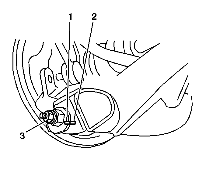
- Align the match marks (1, 2) and install the nut (3) and the bolt that retains the rear of the left rear lower control arm to the knuckle.
- Align the match marks and install the nut and the bolt that retains the rear of the right rear lower control arm to the knuckle.
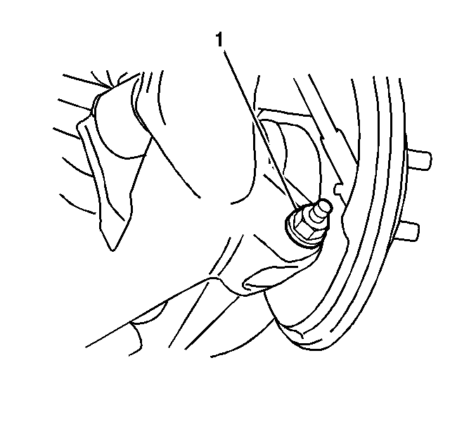
- Install the nut (1) and the bolt that retains the front of the left rear lower control arm to the knuckle.
- Install the nut and the bolt that retains the front of the right rear lower control arm to the knuckle.
- Bleed the brake system. Refer to Hydraulic Brake System Bleeding in Hydraulic Brakes.
- Measure the wheel alignment. Adjust if necessary. Refer to Wheel Alignment Measurement in Wheel Alignment.
Important: Do not tighten the nuts or the bolts on the suspension components. The weight of the vehicle must be on the tire and wheel assemblies before tightening the nuts and the bolts.
Notice: Refer to Fastener Notice in the Preface section.

Tighten
Tighten the nuts and the bolts to 105 N·m
(77.4 lb ft).

Tighten
Tighten the bolts to 65 N·m (47.9 lb ft).
Tighten
Tighten the bolts to 65 N·m (47.9 lb ft).
Tighten
Tighten the brake pipe fitting to 15 N·m
(11.1 lb ft).
Tighten
Tighten the brake pipe fitting to 15 N·m
(11.1 lb ft).
Important: The weight of the vehicle must be on the tire and wheel assemblies.
Tighten
Tighten the nut and the bolt to 74 N·m
(54.6 lb ft).
Tighten
Tighten the nut and the bolt to 74 N·m
(54.6 lb ft).
Tighten
Tighten the nut and the bolt to 74 N·m
(54.6 lb ft).
Tighten
Tighten the nut and the bolt to 74 N·m
(54.6 lb ft).
Tighten
Tighten the nut and the bolt to 74 N·m
(54.6 lb ft).
Tighten
Tighten the nut and the bolt to 74 N·m
(54.6 lb ft).
Tighten
Tighten the nut and the bolt to 140 N·m
(103.3 lb ft).
Tighten
Tighten the nut and the bolt to 140 N·m
(103.3 lb ft).
Tighten
Tighten the nut and the bolt to 74 N·m
(54.6 lb ft).
Tighten
Tighten the nut and the bolt to 74 N·m
(54.6 lb ft).
Tighten
Tighten the nut and the bolt to 74 N·m
(54.6 lb ft).
Tighten
Tighten the nut and the bolt to 74 N·m
(54.6 lb ft).
