For 1990-2009 cars only
Parking Brake Adjustment Drum Brakes
Inspection Procedure
- Raise and support the vehicle. Refer to Lifting and Jacking the Vehicle in General Information.
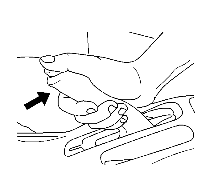
- Pull the park brake lever with approximately 20 kg (44.1 lb) of force.
- Count the number of clicks or ratchet notches.
- Attempt to rotate the rear wheels. Verify the rear wheels do not rotate.
- Release the park brake.
- Attempt to rotate the rear wheels. Verify the rear wheels rotate freely.
- Turn the ignition switch to the ON position. Verify the red BRAKE warning indicator is OFF.
- If the park brake lever travel is correct, lower the vehicle.
- If the park brake lever travel is not correct, complete the Adjustment Procedure.
Specification
| • | The minimum number of clicks is 5. |
| • | The maximum number of clicks is 7. |
Adjustment Procedure
- Remove the drum brake adjuster hole cover.
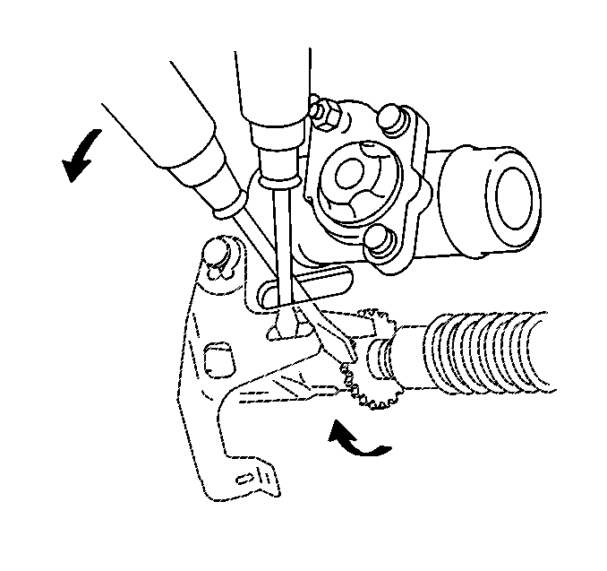
- Insert a screwdriver through the hole in the backing plate. Hold the automatic adjusting lever away from the adjusting bolt.
- Use another screwdriver in order to turn the adjusting bolt. Turn the adjusting bolt down in order to expand the brake shoes until the drum locks.
- Turn the adjusting bolt up 8 notches in order to adjust the shoes to the proper distance away from the drum.
- Install the adjuster hole cover.
- Remove the rear center console. Refer to Rear Floor Console Replacement in Instrument Panel Gages and Console.
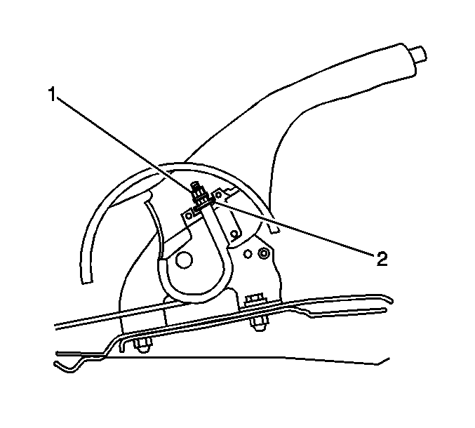
- Loosen the lock nut (1).
- Turn the adjusting nut (2) in order to adjust the park brake lever travel. Refer to the Inspection Procedure above.
- Tighten the lock nut.
- Install the rear center console. Refer to Rear Floor Console Replacement in Instrument Panel Gages and Console.
Tighten
Tighten the nut to 5.0 N·m (44.25 lb in)
Parking Brake Adjustment Disc Brakes
Inspection Procedure
- Raise and support the vehicle. Refer to Lifting and Jacking the Vehicle in General Information.
- Pull the park brake lever with approximately 20 kg (44.1 lb) of force.
- Count the number of clicks or ratchet notches.
- Attempt to rotate the rear wheels. Verify the rear wheels do not rotate.
- Release the park brake.
- Attempt to rotate the rear wheels. Verify the rear wheels rotate freely.
- Turn the ignition switch to the ON position. Verify the red BRAKE warning indicator is OFF.
- If the park brake lever travel is correct, lower the vehicle.
- If the park brake lever travel is not correct, complete the Adjustment Procedure.
Specification
| • | The minimum number of clicks is 5. |
| • | The maximum number of clicks is 7. |
Adjustment Procedure
- Remove the rear tire and wheel assemblies. Refer to Tire and Wheel Removal and Installation in Tires and Wheels.
- Remove the park brake adjuster hole cover from the rear disc.
- Insert a screwdriver through the hole in the disc.
- Use the screwdriver in order to turn the adjusting bolt. Turn the adjusting bolt down in order to expand the brake shoes until the disc locks.
- Turn the adjusting bolt up 8 notches in order to adjust the shoes to the proper distance away from the drum portion of the rear disc.
- Install the adjuster hole cover.
- Install the rear tire and wheel assemblies. Refer to Tire and Wheel Removal and Installation in Tires and Wheels.
- Remove the rear center console. Refer to Rear Floor Console Replacement in Instrument Panel Gages and Console.
- Loosen the lock nut (1).
- Turn the adjusting nut (2) in order to adjust the park brake lever travel. Refer to the Inspection Procedure above.
- Tighten the lock nut.
- Install the rear center console. Refer to Rear Floor Console Replacement in Instrument Panel Gages and Console.
Tighten
Tighten the nut to 5.0 N·m (44.25 lb in)
