Removal Procedure
- Use a siphon in order to remove half of the brake fluid from the master cylinder reservoir.
- Raise and support the vehicle. Refer to Lifting and Jacking the Vehicle .
- Remove the tire and wheel assembly from the vehicle. Refer to Tire and Wheel Removal and Installation .
- Use a flat-bladed tool in order to remove the retaining clip (1).
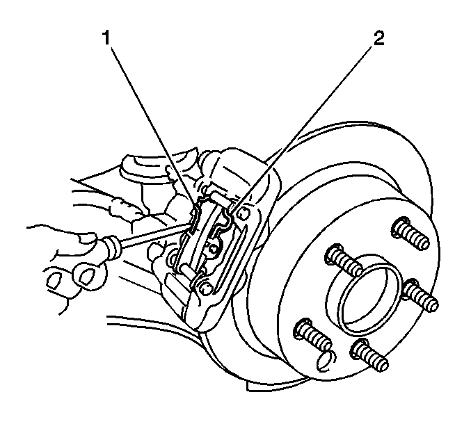
- Use a flat-bladed tool in order to remove the inner spring (1).
- Use a flat-bladed tool in order to remove the outer spring (2).
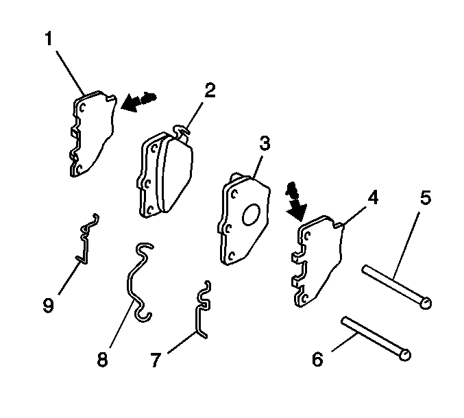
- Remove the pad guide pins (5,6).
- Remove the brake pads (2,3) with the insulators (1,4).
- Remove the insulators from the pads.
Caution: Avoid taking the following actions when you service wheel brake parts:
• Do not grind brake linings. • Do not sand brake linings. • Do not clean wheel brake parts with a dry brush or with compressed air.
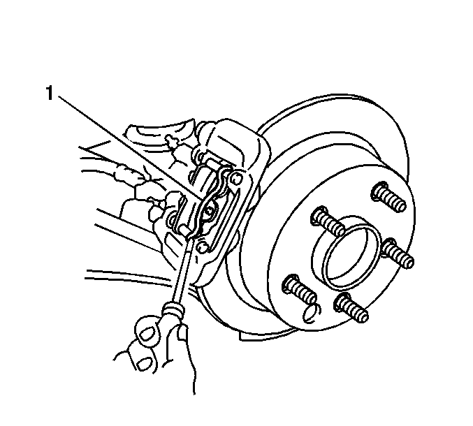
Important: Use care when removing the retaining clip and the springs in order to re-use the components.
Inspection Procedure
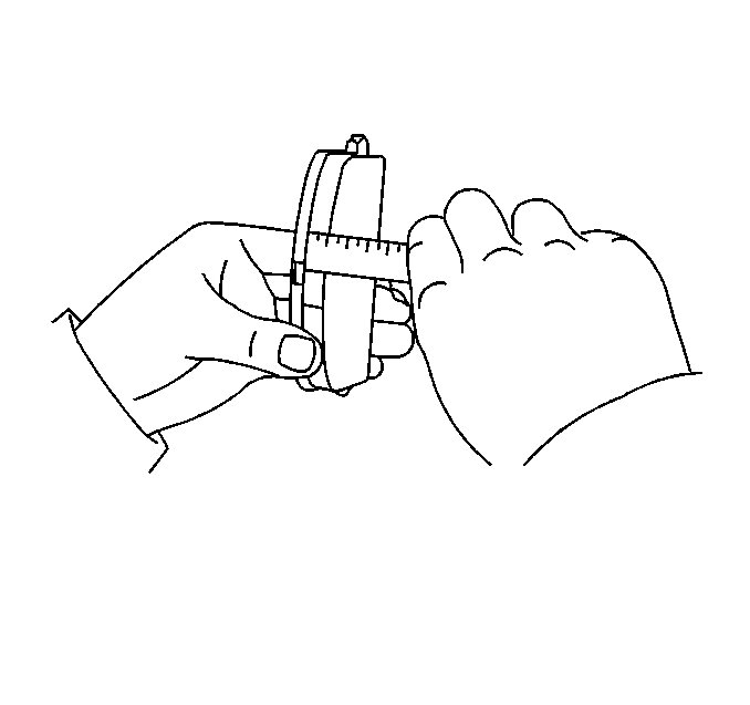
- Inspect the brake pads for wear. If the pad thickness is less than the specification, replace the disc brake pads in axle sets.
- Clean and inspect the disc brake hardware. Replace components if necessary. Refer to Rear Disc Brake Mounting and Hardware Inspection .
- Clean and inspect the caliper. Repair or replace components as necessary. Refer to Brake Caliper Inspection .
- Measure the brake rotor thickness. Refinish or replace the rotor as necessary. Refer to Brake Rotor Thickness Measurement .
- Measure the brake rotor thickness variation. Refinish or replace the rotor as necessary. Refer to Brake Rotor Thickness Variation Measurement .
- Inspect the surface of the brake rotor. Refinish or replace the rotor as necessary. Refer to Brake Rotor Surface and Wear Inspection .
- Measure the brake rotor assembled lateral runout. Refinish or replace the rotor as necessary. Refer to Brake Rotor Assembled Lateral Runout Measurement .
Specification
The minimum brake pad lining thickness is 1 mm (0.039 in).
Important: Refinish or replace the rotor ONLY if the condition of the rotor requires service. DO NOT refinish the rotor if the brake pads are the only components requiring service.
Installation Procedure
- If the caliper piston (13) is not compressed into the caliper bore, complete the following steps:
- Apply disc brake grease to the pad side of the inner pad insulator (1).
- Install the inner pad insulator to the inner brake pad backing plate (2).
- Install the inner brake pad to the caliper with the wear indicator facing upward.
- Apply disc brake grease to the pad side of the outer pad insulator (4).
- Install the outer pad insulator to the outer brake pad backing plate (3).
- Install the outer brake pad to the caliper.
- Install the 2 guide pins (5, 6) to the caliper.
- Install the upper end of the outer spring (7) to the upper guide pin (5).
- Install the lower end of the outer spring to the hole in the outer brake pad backing plate.
- Install the upper end of the inner spring (9) to the upper guide pin.
- Install the lower end of the inner spring to the hole in the inner brake pad backing plate.
- Install the upper end of the retaining clip (8) to the hole in the upper guide pin.
- Install the lower end of the retaining clip to the hole in the lower guide pin (6).
- Verify the ends of the retaining clip are fully inserted into the holes in the guide pins.
- Install the tire and wheel assembly to the vehicle. Refer to Tire and Wheel Removal and Installation .
- Lower the vehicle.
- With the engine OFF, gradually apply and release the brake pedal several times in order to position the caliper pistons and the brake pads.
- Fill the master cylinder fluid reservoir. Refer to Master Cylinder Reservoir Filling .
- Burnish the pads and the rotors. Refer to Brake Pad and Rotor Burnishing .
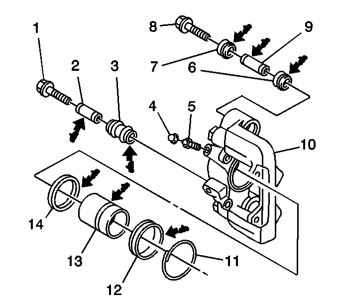
| 1.1. | Wrap the handle of a hammer with tape. |
| 1.2. | Use the handle of a hammer in order to compress the caliper piston into the caliper bore. |

