Heated Oxygen Sensor Replacement - Sensor 1 FWD
Removal Procedure
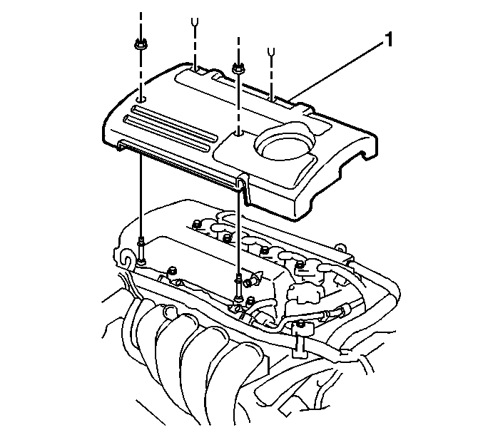
- Remove the 2 fasteners.
- Remove the 2 plastic retainers.
- Remove the engine cover (1) from the engine.
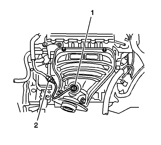
- Disconnect the HO2S 1 electrical connector.
- Remove the HO2S 1 (1) from the exhaust manifold (2).
Notice: The heated oxygen sensors each use a permanently attached pigtail and connector. Do not remove the pigtail from the heated oxygen sensor. Damage or removal of the pigtail or the connector affects proper operation of the heated oxygen sensor. Handle the oxygen sensor carefully. Do not drop the oxygen sensor. Keep the in-line connector and the louvered end free of grease, dirt, or other contaminants. Do not use cleaning solvents of any type. Do not repair the wiring, the connector, or the terminals. Replace the oxygen sensor if the pigtail wiring, the terminals, or the connector is damaged. Proper oxygen sensor operation requires an external air reference. This external air reference is obtained by way of the oxygen sensor signal and heater wires. Any attempt to repair the wires, the connectors, or the terminals results in the obstruction of the air reference and degrades the oxygen sensor performance. A dropped oxygen sensor is a bad oxygen sensor.
Important: The HO2S may be difficult to remove at temperatures exceeding 48°C (120°F). Allow the engine to cool down before attempting to remove the HO2S. Use care in order to prevent any damage to the threads in the exhaust pipe.


Installation Procedure
Important: The HO2S 1 comes with an anti-seize coating on the new sensor. Take precautions in order to prevent removal of any of this coating prior to installation.
- Install the HO2S 1 (1) into the exhaust manifold.
- Tighten the HO2S 1.
- Connect the electrical connector (2) of the HO2S 1.
- Install the engine cover (1).
- Secure the engine cover (1) with the 2 fasteners.
- Install the 2 plastic retainers.

Notice: Replacement components must be the correct part number for the application. Components requiring the use of the thread locking compound, lubricants, corrosion inhibitors, or sealants are identified in the service procedure. Some replacement components may come with these coatings already applied. Do not use these coatings on components unless specified. These coatings can affect the final torque, which may affect the operation of the component. Use the correct torque specification when installing components in order to avoid damage.
Tighten
Tighten the HO2S 1 to 44 N·m (32 lb ft).

Tighten
Tighten the two fasteners to 7 N·m (62 lb in).
Heated Oxygen Sensor Replacement - Sensor 1 AWD
Removal Procedure
- Remove the 2 fasteners.
- Remove the 2 plastic retainers.
- Remove the engine cover (1) from the engine.
- Disconnect the HO2S 1 electrical connector.
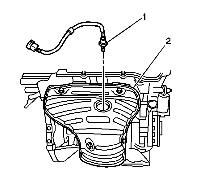
- Remove the HO2S 1 (1) from the exhaust manifold (2).
Notice: The heated oxygen sensors each use a permanently attached pigtail and connector. Do not remove the pigtail from the heated oxygen sensor. Damage or removal of the pigtail or the connector affects proper operation of the heated oxygen sensor. Handle the oxygen sensor carefully. Do not drop the oxygen sensor. Keep the in-line connector and the louvered end free of grease, dirt, or other contaminants. Do not use cleaning solvents of any type. Do not repair the wiring, the connector, or the terminals. Replace the oxygen sensor if the pigtail wiring, the terminals, or the connector is damaged. Proper oxygen sensor operation requires an external air reference. This external air reference is obtained by way of the oxygen sensor signal and heater wires. Any attempt to repair the wires, the connectors, or the terminals results in the obstruction of the air reference and degrades the oxygen sensor performance. A dropped oxygen sensor is a bad oxygen sensor.
Important: The HO2S may be difficult to remove at temperatures exceeding 48°C (120°F). Allow the engine to cool down before attempting to remove the HO2S. Use care in order to prevent any damage to the threads in the exhaust pipe.


Installation Procedure
Important: The HO2S 1 comes with an anti-seize coating on the new sensor. Take precautions in order to prevent removal of any of this coating prior to installation.
- Install the HO2S 1 (1) into the exhaust manifold (2).
- Tighten the HO2S 1.
- Connect the electrical connector of the HO2S 1.
- Install the engine cover (1).
- Secure the engine cover (1) with the 2 fasteners.
- Install the 2 plastic retainers.

Notice: Replacement components must be the correct part number for the application. Components requiring the use of the thread locking compound, lubricants, corrosion inhibitors, or sealants are identified in the service procedure. Some replacement components may come with these coatings already applied. Do not use these coatings on components unless specified. These coatings can affect the final torque, which may affect the operation of the component. Use the correct torque specification when installing components in order to avoid damage.
Tighten
Tighten the HO2S 1 to 44 N·m (32 lb ft).

Tighten
Tighten the two fasteners to 7 N·m (62 lb in).
