| Table 1: | Glass Hatch Actuator Switch |
| Table 2: | Glass Hatch Actuator Switch/Tailgate Courtesy Switch Diode |
| Table 3: | LH Front Door Lock Actuator |
| Table 4: | LH Door Window/Lock Switch |
| Table 5: | LH Rear Door Lock Actuator |
| Table 6: | LH Outside Rear View Mirror Assembly |
| Table 7: | LH Front Window Motor |
| Table 8: | LH Rear Window Motor |
| Table 9: | LH Rear Window Switch |
| Table 10: | Multifunction Alarm Module C2 |
| Table 11: | RH Front Door Lock Actuator |
| Table 12: | RH Door Lock Switch |
| Table 13: | RH Front Window Motor |
| Table 14: | RH Front Window Switch |
| Table 15: | RH Outside Rear View Mirror Assembly |
| Table 16: | RH Rear Window Motor |
| Table 17: | RH Rear Window Switch |
| Table 18: | RH Rear Door Lock Actuator |
| Table 19: | Tailgate Door Lock Actuator |
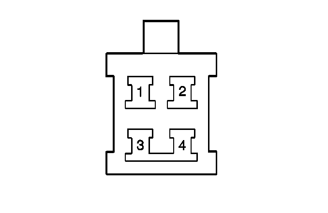
| Table 20: | Glass Hatch Actuator and Courtesy Switch |
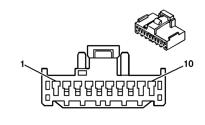
| Table 21: | Power Mirror Switch |
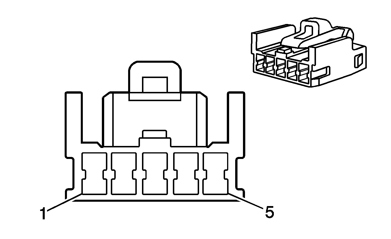
| ||||||
|---|---|---|---|---|---|---|
Connector Part Information |
| |||||
Pin | Wire Color | Function | ||||
1 | -- | Not Used | ||||
2 | BU/WH | Glass Hatch Release Signal | ||||
3 | WH/BK | Ground | ||||
4-5 | -- | Not Used | ||||
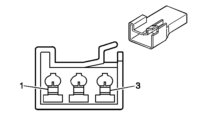
| ||||||
|---|---|---|---|---|---|---|
Connector Part Information |
| |||||
Pin | Wire Color | Function | ||||
1 | RD/WH | Glass Hatch Release Signal | ||||
2 | RD | Courtesy Switch Signal | ||||
3 | RD/BK | Tailgate Courtesy Lamp Signal | ||||
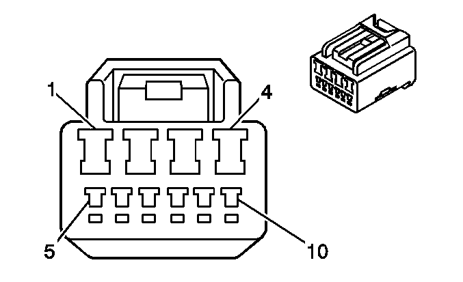
| ||||||
|---|---|---|---|---|---|---|
Connector Part Information |
| |||||
Pin | Wire Color | Function | ||||
1 | RED | Left Front Door Unlock Signal | ||||
2-3 | -- | Not Used | ||||
4 | BU | Left Front Door Lock Signal | ||||
5-6 | -- | Not Used | ||||
7 | WH/BK | Ground | ||||
8 | WH | Unlock Detection Signal | ||||
9 | GN | Lock Signal | ||||
10 | BU/YL | Unlock Signal | ||||
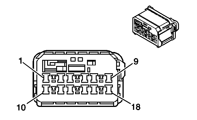
| ||||||
|---|---|---|---|---|---|---|
Connector Part Information |
| |||||
Pin | Wire Color | Function | ||||
1 | WH/BK | Ground | ||||
2 | -- | Not Used | ||||
3 | WH/BK | Left Front Door Lock Switch Ground | ||||
4 | YE | Left Front Window Motor Up Supply Voltage | ||||
5 | BU/WH | Lock Signal | ||||
6 | BK | Left Front Window Switch Supply Voltage | ||||
7 | BK | Left Front Window Switch Supply Voltage | ||||
8 | BU | Unlock Signal | ||||
9 | GN | Left Front Window Motor Down Supply Voltage | ||||
10 | RD/BK | Right Rear Window Switch Up Voltage | ||||
11 | -- | Not Used | ||||
12 | RD/BU | Left Rear Window Switch Up Voltage | ||||
13 | BU | Left Rear Window Switch Down Voltage | ||||
14 | -- | Not Used | ||||
15 | BK/WT | Right Front Window Switch Down Voltage | ||||
16 | RD | Right Rear Window Switch Down Voltage | ||||
17 | -- | Not Used | ||||
18 | BK/RD | Right Front Window Switch Up Voltage | ||||

| ||||||
|---|---|---|---|---|---|---|
Connector Part Information |
| |||||
Pin | Wire Color | Function | ||||
1 | RD | Unlock Signal | ||||
2-3 | -- | Not Used | ||||
4 | BU | Lock Signal | ||||
5-10 | -- | Not Used | ||||
| ||||||
|---|---|---|---|---|---|---|
Connector Part Information |
| |||||
Pin | Wire Color | Function | ||||
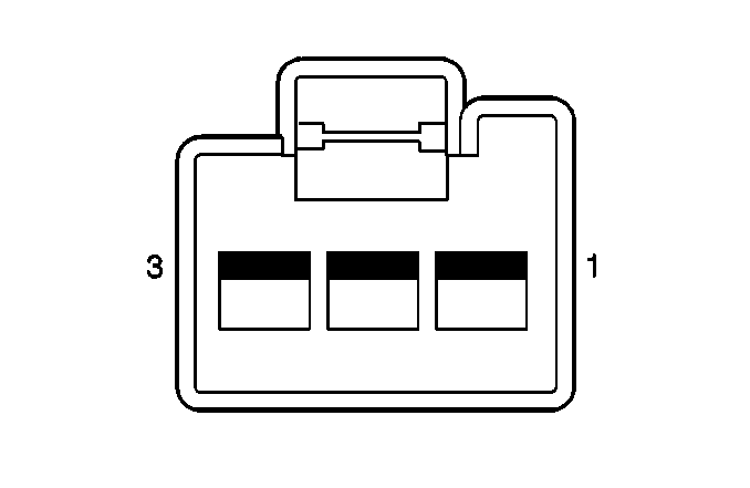
1 | BU | Up/Down Motor | ||||
2 | BN/WT | Motor Common | ||||
3 | LT GN | Left/Right Motor | ||||
| ||||||
|---|---|---|---|---|---|---|
Connector Part Information |
| |||||
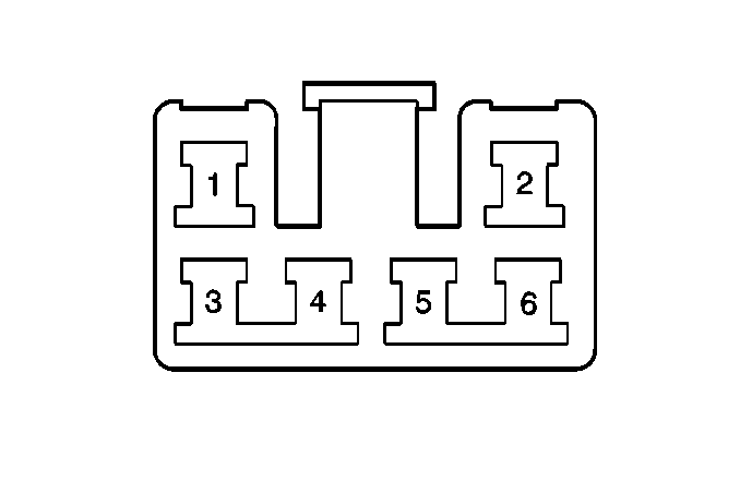
Pin | Wire Color | Function | ||||
1-3 | -- | Not Used | ||||
4 | YL | Up Voltage | ||||
5 | GN | Down Voltage | ||||
6 | -- | Not Used | ||||

| ||||||
|---|---|---|---|---|---|---|
Connector Part Information |
| |||||
Pin | Wire Color | Function | ||||
1-3 | -- | Not Used | ||||
4 | GN | Down Voltage | ||||
5 | YL | Up Voltage | ||||
6 | -- | Not Used | ||||
| ||||||
|---|---|---|---|---|---|---|
Connector Part Information |
| |||||
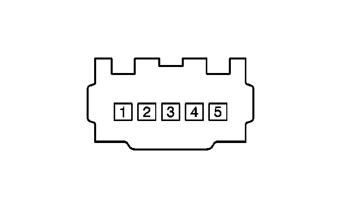
Pin | Wire Color | Function | ||||
1 | BU/RD | Master Down Signal | ||||
2 | GN | Motor Down Signal | ||||
3 | BK | Ignition Positive Voltage | ||||
4 | YL | Motor Up Signal | ||||
5 | RD/BK | Master Up Signal | ||||
| ||||||
|---|---|---|---|---|---|---|
Connector Part Information |
| |||||
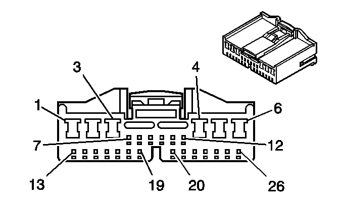
Pin | Wire Color | Function | ||||
1 | RD | Left Front Door Unlock Control | ||||
2 | WT | Glass Hatch Supply Voltage | ||||
3 | RD/WT | Instrument Panel Lamp Dimmer Signal | ||||
4 | -- | Not Used | ||||
5 | BU/BK | Right Front Key Cylinder Unlock Signal | ||||
6 | BU/YL | Left Front Key Cylinder Unlock Signal | ||||
7 | GN | Left Front Key Cylinder Lock Signal | ||||
8 | BU | Left/Right Front Door Unlock Switch Signal | ||||
9 | BU/WT | Left/Right Front Door Lock Switch Signal | ||||
10 | GN/YL | Horn Relay Control | ||||
11 | RD | Headlamps Signal | ||||
12 | -- | Not Used | ||||
13 | RD/WT | Door Open Signal | ||||
14-17 | -- | Not Used | ||||
18 | WT/RD | Right Front Door Unlock Detection Signal | ||||
19 | WT | Left Front Door Unlock Detection Signal | ||||
20-22 | -- | Not Used | ||||
23 | BU/WT | Glass Hatch Actuator Signal | ||||
24 | PL/WT | PCM Vehicle Speed Input Signal | ||||
25 | YL/BK | Hazard Switch Signal | ||||
26 | WT | Theft Deterent Module Door Signal Input | ||||

| ||||||
|---|---|---|---|---|---|---|
Connector Part Information |
| |||||
Pin | Wire Color | Function | ||||
1 | RD | Unlock Signal | ||||
2-3 | -- | Not Used | ||||
4 | BU | Lock Signal | ||||
5 | BU/BK | Unlock Signal--Key Cylinder | ||||
6 | GN | Lock Signal--Key Cylinder | ||||
7 | WT/RD | Lock Detection--Key Switch | ||||
8 | WT/BK | Ground | ||||
9-10 | -- | Not Used | ||||

| ||||||
|---|---|---|---|---|---|---|
Connector Part Information |
| |||||
Pin | Wire Color | Function | ||||
1-2 | -- | Not Used | ||||
3 | WT/BK | Ground | ||||
4 | -- | Not Used | ||||
5 | BU | Unlock Signal | ||||
6 | BU/WT | Lock Signal | ||||

| ||||||
|---|---|---|---|---|---|---|
Connector Part Information |
| |||||
Pin | Wire Color | Function | ||||
1-3 | -- | Not Used | ||||
4 | GN | Down Input | ||||
5 | YL | Up Input | ||||
6 | -- | Not Used | ||||

| ||||||
|---|---|---|---|---|---|---|
Connector Part Information |
| |||||
Pin | Wire Color | Function | ||||
1 | GN | Motor Down Signal | ||||
2 | BU/WT | Master Down Signal | ||||
3 | YL | Motor Up Signal | ||||
4 | BK | Ignition Positive Voltage | ||||
5 | GN/RD | Master Up Signal | ||||

| ||||||
|---|---|---|---|---|---|---|
Connector Part Information |
| |||||
Pin | Wire Color | Function | ||||
1 | RD | Left/Right Motor | ||||
2 | BN/WT | Motor Common | ||||
3 | RD/WT | Up/Down Motor | ||||

| ||||||
|---|---|---|---|---|---|---|
Connector Part Information |
| |||||
Pin | Wire Color | Function | ||||
1-3 | -- | Not Used | ||||
4 | GN | Down Input | ||||
5 | YL | Up Input | ||||
6 | -- | Not Used | ||||

| ||||||
|---|---|---|---|---|---|---|
Connector Part Information |
| |||||
Pin | Wire Color | Function | ||||
1 | BU/RED | Master Down Signal | ||||
2 | GN | Motor Down Voltage | ||||
3 | BK | Switch Supply Voltage | ||||
4 | YL | Motor Up Voltage | ||||
5 | RD/BK | Master Up Signal | ||||

| ||||||
|---|---|---|---|---|---|---|
Connector Part Information |
| |||||
Pin | Wire Color | Function | ||||
1 | RD | Unlock Signal | ||||
2-3 | -- | Not Used | ||||
4 | BU | Lock Signal | ||||
5-10 | -- | Not Used | ||||
| ||||||
|---|---|---|---|---|---|---|
Connector Part Information |
| |||||
Pin | Wire Color | Function | ||||
1 | WT/BK | Ground | ||||
2 | RD/BK | Courtesy Lamp Switch Signal | ||||
3 | RD | Unlock Signal | ||||
4 | BU | Lock Signal | ||||

| ||||||
|---|---|---|---|---|---|---|
Connector Part Information |
| |||||
Pin | Wire Color | Function | ||||
1 | WT/BK | Ground | ||||
2 | RD/WT | Courtesy Lamp Switch Signal | ||||
3 | WT | Actuator Supply Voltage | ||||
4 | WT/BK | Ground | ||||
| ||||||
|---|---|---|---|---|---|---|
Connector Part Information |
| |||||
Pin | Wire Color | Function | ||||
1 | -- | Not Used | ||||
2 | RD | RH Mirror--Left/Right Motor Voltage | ||||
3 | RD/WT | RH Mirror--Up/Down Motor Voltage | ||||
4 | LT GN | LH Mirror--Up/Down Motor Voltage | ||||
5 | BU | LH Mirror--Left/Right Motor Voltage | ||||
6 | BN/WT | RH/LH Mirror Motor Common | ||||
7 | WT/BK | Ground | ||||
8 | GY | Ignition Positive Voltage | ||||
9-10 | -- | Not Used | ||||
