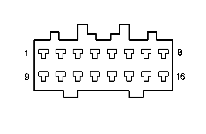
| Table 1: | Vehicle Communication Interface Module C1 |
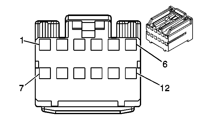
| Table 2: | Vehicle Communication Interface Module C2 |
| Table 3: | Vehice Interface Unit |

| ||||||
|---|---|---|---|---|---|---|
Connector Part Information |
| |||||
Pin | Wire Color | Function | ||||
1 | -- | Not Used | ||||
2 | BK/OR | Rearview Mirror Indicator | ||||
3 | BK/YE | Rearview Mirror Illumination | ||||
4 | -- | Not Used | ||||
5 | BK/WH | Ground | ||||
6 | BK/RD | Accessory | ||||
7 | -- | Not Used | ||||
8 | WH/BK | Ground | ||||
9-10 | -- | Not Used | ||||
11 | BK/BU | Signal | ||||
12- 15 | -- | Not Used | ||||
16 | BK | Battery Supply Voltage | ||||

| ||||||
|---|---|---|---|---|---|---|
Connector Part Information |
| |||||
Pin | Wire Color | Function | ||||
1 | BK | Speaker Output Positive | ||||
2 | WH | Speaker Output Negative | ||||
3- 4 | -- | Not Used | ||||
5 | BU/RD | Battery Positive Voltage | ||||
6- 7 | -- | Not Used | ||||
8 | BARE | Drain Wire | ||||
9 | BK | Microphone Positive | ||||
10 | BARE | Drain Wire | ||||
11- 12 | -- | Not Used | ||||

| ||||||
|---|---|---|---|---|---|---|
Connector Part Information |
| |||||
Pin | Wire Color | Function | ||||
1 | BU/RD | Antenna Signal | ||||
2 | BU/RD | Serial Data | ||||
3 | BU/BK | Right Front Door Lock Actuator Signal | ||||
4 | GN/YE | Horn Relay Signal | ||||
5 | YE/BK | Hazard Switch Signal | ||||
6-8 | -- | Not Used | ||||
9 | BU | SIR Voltage | ||||
10-11 | -- | Not used | ||||
12 | GY | Battery Positive Voltage | ||||
13 | BK/WH | Ignition Switch - Start Voltage | ||||
14 | BK | Battery Positive Voltage | ||||
15 | WH/BK | Ground | ||||
16 | -- | Not used | ||||
