For 1990-2009 cars only
Tools Required
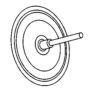
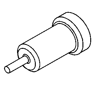
| • | J 41013 Rotor Resurfacing Kit |
| • | J 42450-A Wheel Hub Resurfacing Kit |
Removal Procedure
- Raise and support the vehicle. Refer to Lifting and Jacking the Vehicle .
- Remove the tire and wheel assembly. Refer to Tire and Wheel Removal and Installation .
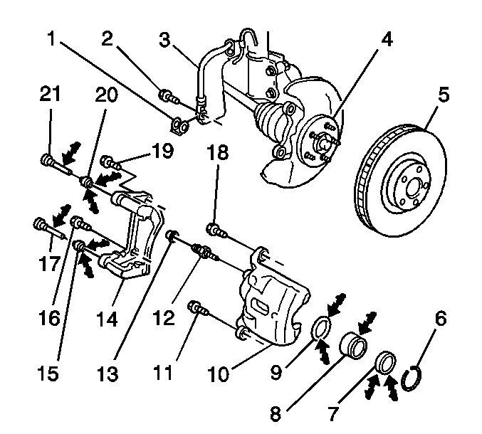
- Remove the brake caliper and the caliper mounting bracket (14) as an assembly from the suspension knuckle and support the assembly with heavy mechanic's wire, or equivalent. Verify that there is no tension on the hydraulic brake flexible hose. Refer to Front Brake Caliper Bracket Replacement .
- Use paint in order to mark the position of the brake rotor (5) to the hub (4).
- Remove the brake rotor.
Notice: Support the brake caliper with heavy mechanic wire, or equivalent, whenever it is separated from its mount and the hydraulic flexible brake hose is still connected. Failure to support the caliper in this manner will cause the flexible brake hose to bear the weight of the caliper, which may cause damage to the brake hose and in turn may cause a brake fluid leak.
Important: Do NOT disconnect the hydraulic brake flexible hose from the caliper.
Installation Procedure
- Use the J 42450-A , or equivalent, in order to clean the mating surface of the hub flange (4).
- Use denatured alcohol, or an equivalent brake cleaner, in order to clean the hub.
- Use the J 41013 , or equivalent, in order to clean the mating surface of the brake rotor.
- Use denatured alcohol, or an equivalent brake cleaner, in order to clean the rotor.
- Inspect the mating surfaces of the hub and the rotor. Verify that there are no foreign particles or debris remaining.
- Install the brake rotor to the hub. If you are installing the old brake rotor, align the paint marks in order to install the brake rotor in the original position on the hub.
- If you removed and installed the old brake rotor as part of a brake system repair, measure the assembled lateral runout (LRO) of the brake rotor in order to ensure optimum performance of the disc brakes. Refer to Brake Rotor Assembled Lateral Runout Measurement .
- If the brake rotor assembled LRO measurement exceeds the specification, adjust the LRO to the specification. Refer to Brake Rotor Assembled Lateral Runout Correction .
- Install the brake caliper and the brake caliper bracket as an assembly to the suspension knuckle. Refer to Front Brake Caliper Bracket Replacement .
- Install the tire and wheel assembly. Refer to Tire and Wheel Removal and Installation .
- Lower the vehicle.
- Press the brake pedal 3 times.
- Verify the brake fluid level is correct. Refer to Master Cylinder Reservoir Filling .
- If you installed new pads or a new rotor, burnish the pads and rotors. Refer to Brake Pad and Rotor Burnishing .
Important: Clean the hub and the brake rotor mating surfaces. Failure to remove corrosion and other contaminants from the hub and the rotor may result in excessive assembled lateral runout (LRO) of the brake rotor, which could lead to brake pulsation.
