| Table 1: | Amplifier C1 (w/U65) |
| Table 2: | Amplifier C2 (w/U65) |
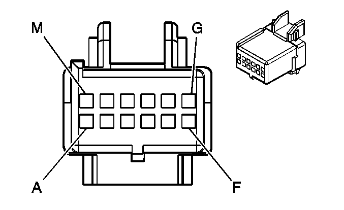
| Table 3: | Digital Radio Receiver |
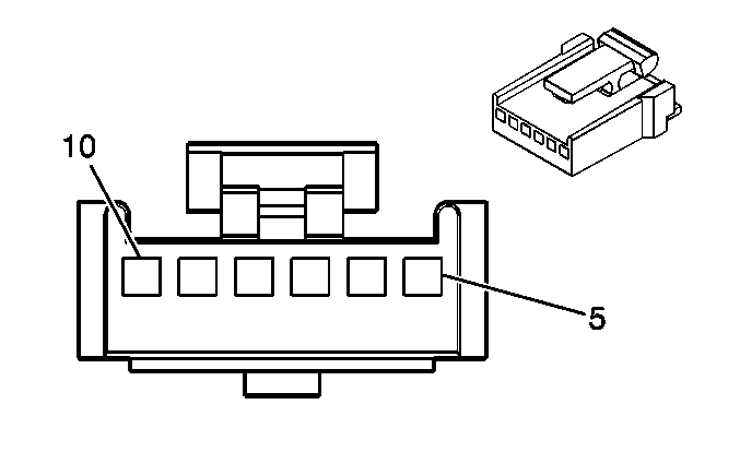
| Table 4: | Remote CD Changer C1 (w/UC6) |
| Table 5: | Remote CD Changer C2 (w/UC6) |
| Table 6: | Noise Filter |
| Table 7: | Radio C1 (w/UW4) |
| Table 8: | Radio C1 (w/U65 - Amplifier) |
| Table 9: | Radio C1 (w/UW5 - Navigation) |
| Table 10: | Radio C2 (w/U65 - Amplifier) |
| Table 11: | Radio C2 (w/UW5 - Navigation) |
| Table 12: | LF Door Speaker (w/UW4, UW5) |
| Table 13: | LF Door Speaker (w/U65) |
| Table 14: | LF Door Tweeter (w/U65) |
| Table 15: | RF Door Speaker (All) |
| Table 16: | RF Door Tweeter (w/U65) |
| Table 17: | LR/RR Door Speaker (All) |
| Table 18: | Subwoofer (U65) |
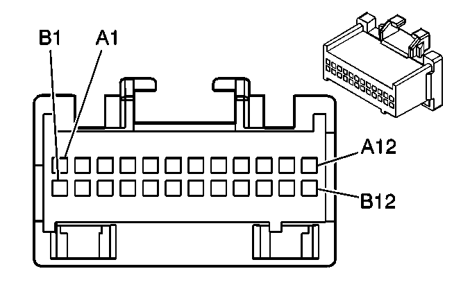
| ||||||
|---|---|---|---|---|---|---|
Connector Part Information |
| |||||
Pin | Wire Color | Function | ||||
A1 | BK/WH | Sensitivity Control | ||||
A2 | -- | Not Used | ||||
A3 | BK | Ignition Positive Voltage | ||||
A4 | BK | Left Rear Audio Input (+) | ||||
A5 | YE | Left Rear Audio Input (-) | ||||
A6 | PU | Left Front Audio Input (-) | ||||
A7 | PK | Left Front Audio Input (+) | ||||
A8 | WH | Mute Control | ||||
A9- A12 | -- | Not Used | ||||
B1 | WH | Right Rear Door Speaker Output (-) | ||||
B2 | RD | Right Rear Door Speaker Output (+) | ||||
B3 | -- | Not Used | ||||
B4 | WH | Right Rear Audio Input (-) | ||||
B5 | RD | Right Rear Audio Input (+) | ||||
B6 | LT GN | Right Front Audio Input (+) | ||||
B7 | BU | Right Front Audio Input (-) | ||||
B8 | -- | Not Used | ||||
B9 | RD/WH | Left Front Door Tweeter Output (+) | ||||
B10 | BU/WH | Left Front Door Tweeter Output (-) | ||||
B11 | GN/WH | Right Front Door Tweeter Output (+) | ||||
B12 | BN | Right front Door Tweeter Output (-) | ||||
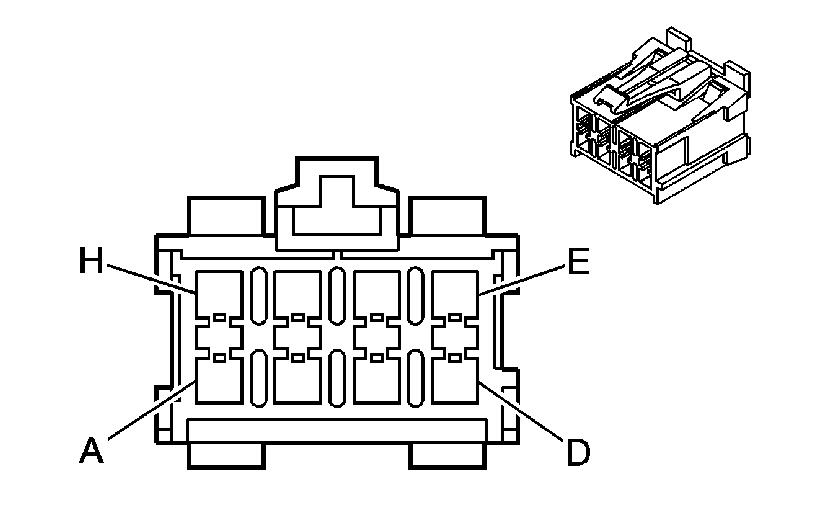
| ||||||
|---|---|---|---|---|---|---|
Connector Part Information |
| |||||
Pin | Wire Color | Function | ||||
A | LT GN | Right Front Door Speaker Output (+) | ||||
B | BU | Right front Door Speaker Output (-) | ||||
C | PU | Left Front Door Speaker Output (-) | ||||
D | PK | Left Front Door Speaker Output (+) | ||||
E | BU/RD | Battery Positive Voltage | ||||
F | WH/BK | Ground | ||||
G | BK | Left Rear Door Speaker Output (+) | ||||
H | YE | Left Rear Door Speaker Output (-) | ||||
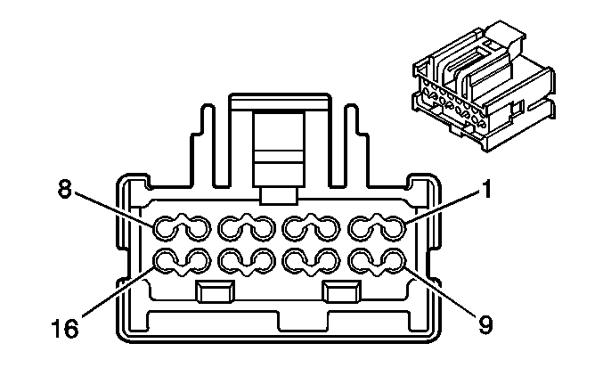
| ||||||
|---|---|---|---|---|---|---|
Connector Part Information |
| |||||
Pin | Wire Color | Function | ||||
1 | -- | Not Used | ||||
2 | BN/WH | Remote Radio Left Audio Signal | ||||
3 | DK GN/WH | Remote Radio Right Audio Signal | ||||
4-8 | -- | Not Used | ||||
9 | BK/WH | Ground | ||||
10 | BK/WH | Audio Common | ||||
11 | BARE | Drain Wire | ||||
12-14 | -- | Not Used | ||||
15 | PU | Class 2 Serial Data | ||||
16 | OR | Battery Positive Voltage | ||||
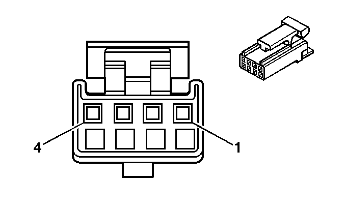
| ||||||
|---|---|---|---|---|---|---|
Connector Part Information |
| |||||
Pin | Wire Color | Function | ||||
1 | WH | Left Audio Output | ||||
2 | BK | Right Audio Output | ||||
3 | RD | Signal Ground | ||||
4 | Braided | Drain Wire | ||||
| ||||||
|---|---|---|---|---|---|---|
Connector Part Information |
| |||||
Pin | Wire Color | Function | ||||
5 | BU/WH | CD Changer Supply Voltage | ||||
6 | -- | Not Used | ||||
7 | WH/BK | Ground | ||||
8-9 | -- | Not Used | ||||
10 | BU | Control Signal | ||||
| ||||||
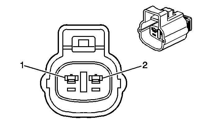
|---|---|---|---|---|---|---|
Connector Part Information |
| |||||
Pin | Wire Color | Function | ||||
1 | BK/WH | Ignition Positive Voltage | ||||
2 | -- | Not Used | ||||

| ||||||
|---|---|---|---|---|---|---|
Connector Part Information |
| |||||
Pin | Wire Color | Function | ||||
A1-A7 | -- | Not Used | ||||
A8 | PK | Left Front Speaker Output (+) | ||||
A9 | PU | Left Front Speaker Output (-) | ||||
A10 | WH | Right Rear Speaker Output (-) | ||||
A11 | RD | Right Rear Speaker Output (+) | ||||
A12 | BN | Ground G201 | ||||
B1 | BU/YE | Battery Positive Voltage | ||||
B2 | GY | Ignition Positive Voltage | ||||
B3 | BK | Antenna Amplifier Supply Voltage | ||||
B4 | GN | LCD Backlighting Control | ||||
B5 | WH/GN | LCD Backlighting Dim ground | ||||
B6-B7 | -- | Not Used | ||||
B8 | BK | Left Rear Speaker Output (+) | ||||
B9 | YE | Left Rear Speaker Output (-) | ||||
B10 | BU | Right Front Speaker Output (-) | ||||
B11 | LT GN | Right Front Speaker Output (+) | ||||
B12 | GN | Park Lamps Input | ||||

| ||||||
|---|---|---|---|---|---|---|
Connector Part Information |
| |||||
Pin | Wire Color | Function | ||||
A1-A7 | -- | Not Used | ||||
A8 | PU | Left Front Speaker Output (+) | ||||
A9 | PU | Left Front Speaker Output (-) | ||||
A10 | WH | Right Rear Speaker Output (-) | ||||
A11 | RD | Right Rear Speaker Output (+) | ||||
A12 | BN | Ground G201 | ||||
B1 | BU/YE | Battery Positive Voltage | ||||
B2 | GY | Ignition Positive Voltage | ||||
B3 | BK | Antenna Amplifier Supply Voltage | ||||
B4 | GN | LCD Backlighting Control | ||||
B5 | WH/GN | LCD Backlighting Dim ground | ||||
B6 | BK/WH | Sensitivity Control | ||||
B7 | -- | Not Used | ||||
B8 | BK | Left Rear Speaker Output (+) | ||||
B9 | YE | Left Rear Speaker Output (-) | ||||
B10 | BU | Right Front Speaker Output (-) | ||||
B11 | LT GN | Right Front Speaker Output (+) | ||||
B12 | GN | Park Lamps Input | ||||

| ||||||
|---|---|---|---|---|---|---|
Connector Part Information |
| |||||
Pin | Wire Color | Function | ||||
A1 | BU | Control Signal | ||||
A2-A7 | -- | Not Used | ||||
A8 | PK | Left Front Speaker Output (+) | ||||
A9 | PU | Left Front Speaker Output (-) | ||||
A10 | WH | Right Rear Speaker Output (-) | ||||
A11 | RD | right Rear Speaker Output (+) | ||||
A12 | BN | Ground G201 | ||||
B1 | BU/WH | Battery Positive Voltage | ||||
B2 | GY | Ignition Positive Voltage | ||||
B3 | BK | Antenna Amplifier Supply Voltage | ||||
B4 | GN | LCD Backlighting Control | ||||
B5 | WH/BK | LCD Backlighting Dim ground | ||||
B6-B7 | -- | Not Used | ||||
B8 | BK | Left Rear Speaker Output (+) | ||||
B9 | YE | Left Rear Speaker Output (-) | ||||
B10 | BU | Right Front Speaker Output (-) | ||||
B11 | LT GN | Right Front Speaker Output (+) | ||||
B12 | GN | Park Lamps Input | ||||
| ||||||
|---|---|---|---|---|---|---|
Connector Part Information |
| |||||
Pin | Wire Color | Function | ||||
A-E | -- | Not Used | ||||
F | WH | Mute Control | ||||
G-M | -- | Not Used | ||||

| ||||||
|---|---|---|---|---|---|---|
Connector Part Information |
| |||||
Pin | Wire Color | Function | ||||
A | -- | Not Used | ||||
B | RD/BK | Backup/Reverse Signal | ||||
C | BARE | Drain Wire | ||||
D | -- | Not Used | ||||
E | PU/WH | Vehicle Speed Signal | ||||
F-G | -- | Not Used | ||||
H | BK | Right Audio Input | ||||
J | WH | Left Audio Input | ||||
K | RD | Signal Ground | ||||
L-M | -- | Not Used | ||||
| ||||||
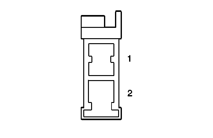
|---|---|---|---|---|---|---|
Connector Part Information |
| |||||
Pin | Wire Color | Function | ||||
1 | PK | Positive | ||||
2 | PU | Negative | ||||

| ||||||
|---|---|---|---|---|---|---|
Connector Part Information |
| |||||
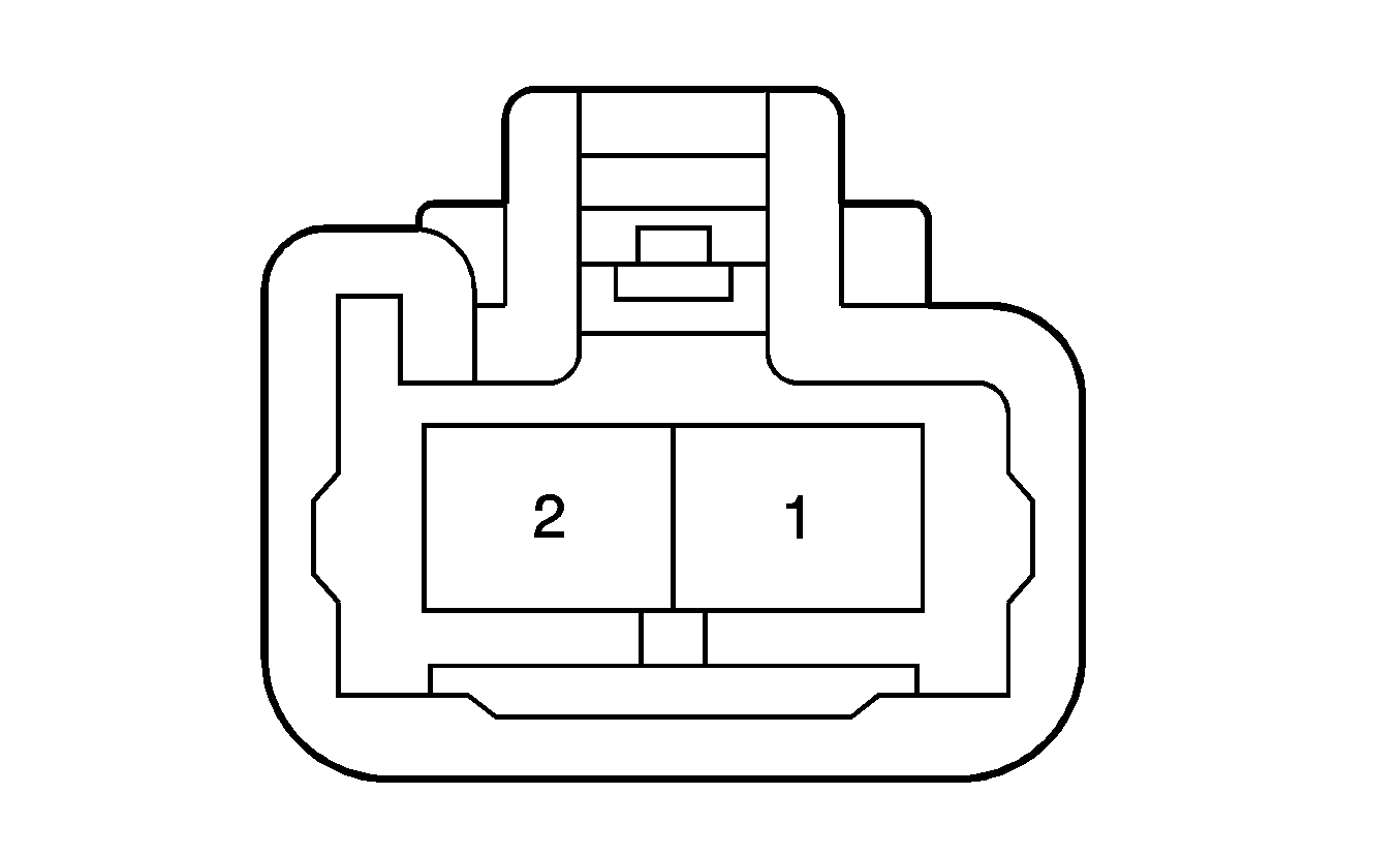
Pin | Wire Color | Function | ||||
1 | RD | Positive | ||||
2 | WH | Negative | ||||
| ||||||
|---|---|---|---|---|---|---|
Connector Part Information |
| |||||
Pin | Wire Color | Function | ||||
1 | PK | Positive | ||||
2 | PU | Negative | ||||

| ||||||
|---|---|---|---|---|---|---|
Connector Part Information |
| |||||
Pin | Wire Color | Function | ||||
1 | LT GN | Positive | ||||
2 | BU | Negative | ||||

| ||||||
|---|---|---|---|---|---|---|
Connector Part Information |
| |||||
Pin | Wire Color | Function | ||||
1 | LT GN | Positive | ||||
2 | BU | Negative | ||||

| ||||||
|---|---|---|---|---|---|---|
Connector Part Information |
| |||||
Pin | Wire Color | Function | ||||
1 | RD | Positive | ||||
2 | WH | Negative | ||||
| ||||||
|---|---|---|---|---|---|---|
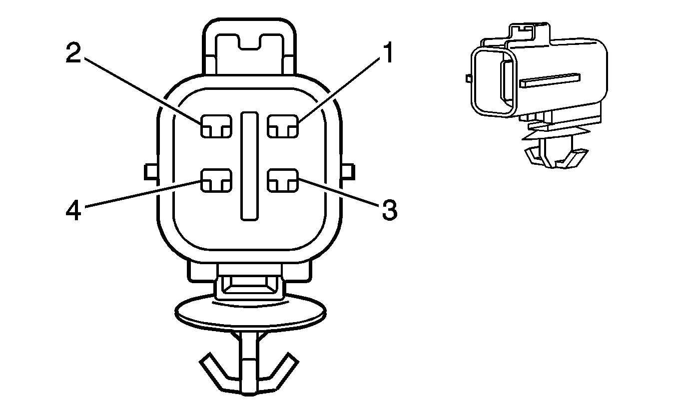
Connector Part Information |
| |||||
Pin | Wire Color | Function | ||||
1 | BU | Subwoofer Positive | ||||
2 | LT GN | Subwoofer Negative | ||||
3 | BK | Subwoofer Positive | ||||
4 | YE | Subwoofer Negative | ||||
