Tools Required
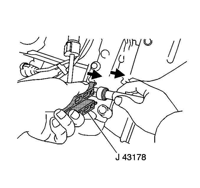
J 43178 Fuel Line Disconnect Tool
Removal Procedure
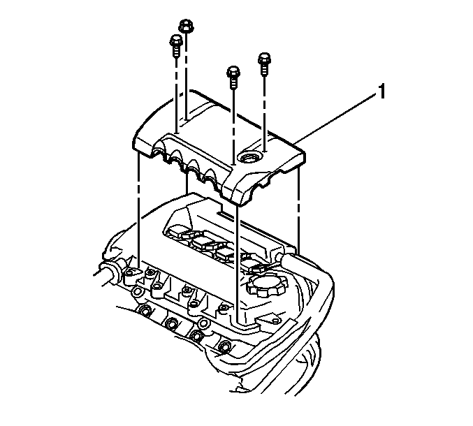
- Remove the four fasteners from the engine cover (1).
- Remove the engine cover (1) from the engine.
- Relieve the fuel pressure. Refer to Fuel Pressure Relief .
- Remove the quick connect coupling cover.
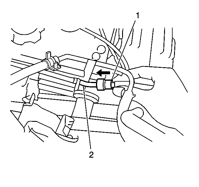
- Disconnect the coupling for the fuel feed hose from the fuel feed pipe of the fuel rail using the J 43178 . Use a shop towel in order to catch any remaining fuel that may leak. Refer to Metal Collar Quick Connect Fitting Service .
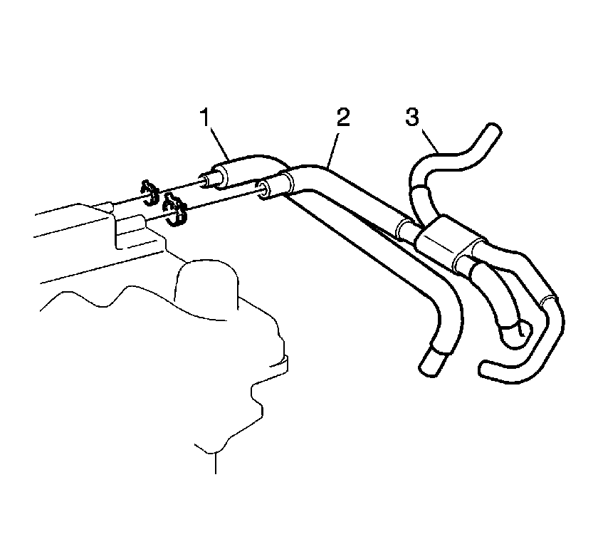
- Disconnect the PCV hose (1) from the PCV valve.
- Disconnect the PCV breather hose (2).
- Disconnect the EVAP hose (3).
- Swing the two PCV hoses and the EVAP hose away from the cylinder head
- Remove the bolt to the ignition coil wire harness bracket.
- Disconnect the electrical connectors to the four fuel injectors.
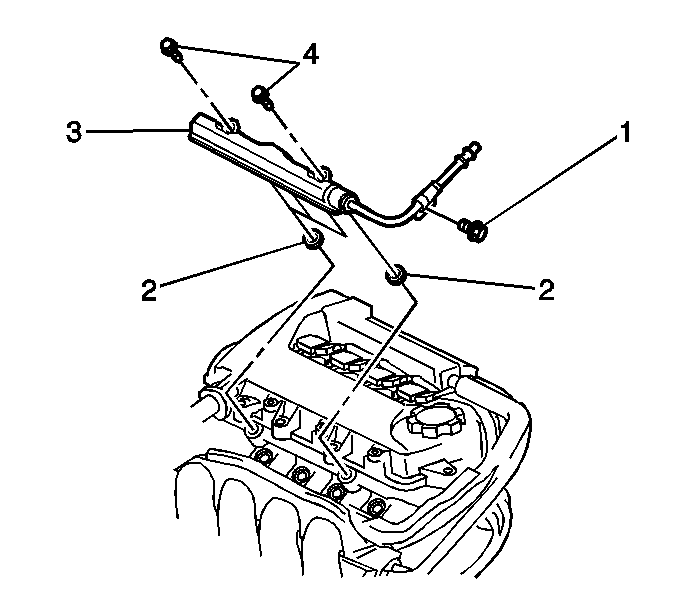
- Remove the fastener (1) from the fuel supply pipe bracket.
- Remove the two fasteners (4) from the fuel rail (3).
- Remove the fuel rail (3) and the spacers (2) from the engine.
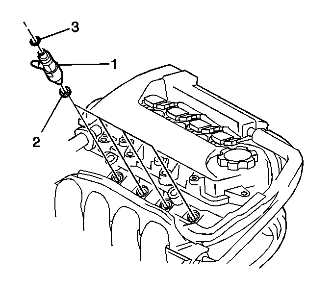
- Remove the fuel injector with the O-rings and with the grommets from the fuel rail.
Installation Procedures
- Install new O-rings (3) and new grommets (2) on the fuel injectors (1).
- Apply clean engine oil to the O-rings (3) and to the grommets (2).
- Install the fuel injectors (1) into the fuel rail.
- Install the fuel rail (3) and the spacers (2) onto the engine.
- Secure the fuel rail to the engine with the 2 fasteners (4).
- Install the fastener (1) to the fuel supply pipe bracket.
- Connect the electrical connectors to the four fuel injectors.
- Install the bolt to the ignition coil wire harness bracket.
- Connect the EVAP hose (3).
- Connect the PCV breather hose (2).
- Connect the PCV hose (1) to the PCV valve.
- Connect the quick-connect fitting (1) for the fuel feed hose to the fuel feed pipe (2) of the fuel rail. Refer to Metal Collar Quick Connect Fitting Service .
- Install the quick connect coupling cover.
- Connect the negative battery cable.
- Turn ON the ignition in order to pressurize the fuel system.
- Turn OFF the ignition.
- Inspect for fuel leaks.
- Repair any fuel leaks as necessary.
- Install the engine cover (1) to the engine.
- Secure the engine cover (1) with the four fasteners.

Notice: Use the correct fastener in the correct location. Replacement fasteners must be the correct part number for that application. Fasteners requiring replacement or fasteners requiring the use of thread locking compound or sealant are identified in the service procedure. Do not use paints, lubricants, or corrosion inhibitors on fasteners or fastener joint surfaces unless specified. These coatings affect fastener torque and joint clamping force and may damage the fastener. Use the correct tightening sequence and specifications when installing fasteners in order to avoid damage to parts and systems.
Tighten
Tighten the fasteners to 29 N·m (21 lb ft).
Tighten
Tighten the fastener to 9 N·m (80 lb in).
Tighten
Tighten the fastener to 10 N·m (89 lb in).

Tighten
Tighten the retainer for the negative battery cable terminal to 15 N·m
(11 lb ft).

Tighten
Tighten the fasteners to 7 N·m (62 lb in).
