For 1990-2009 cars only
- Remove the power steering pump from the vehicle. Refer to Power Steering Pump Replacement .
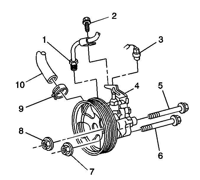
- Thoroughly clean the exterior of the pump (4).
- Remove the bolt and the inlet tube from the pump.
- Remove the inlet tube seal from the inlet tube.
- Remove the pump fitting from the flow control valve.
- Remove the pump fitting seal from the pump fitting.
- Remove the flow control valve from the pump.
- Remove the flow control valve spring.
- Remove the power steering pump pressure switch.
- Remove the 4 bolts and the rear pump housing from the front housing.
- Remove the pump housing seal.
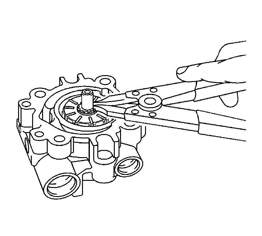
- Remove the retainer ring from the pump shaft.
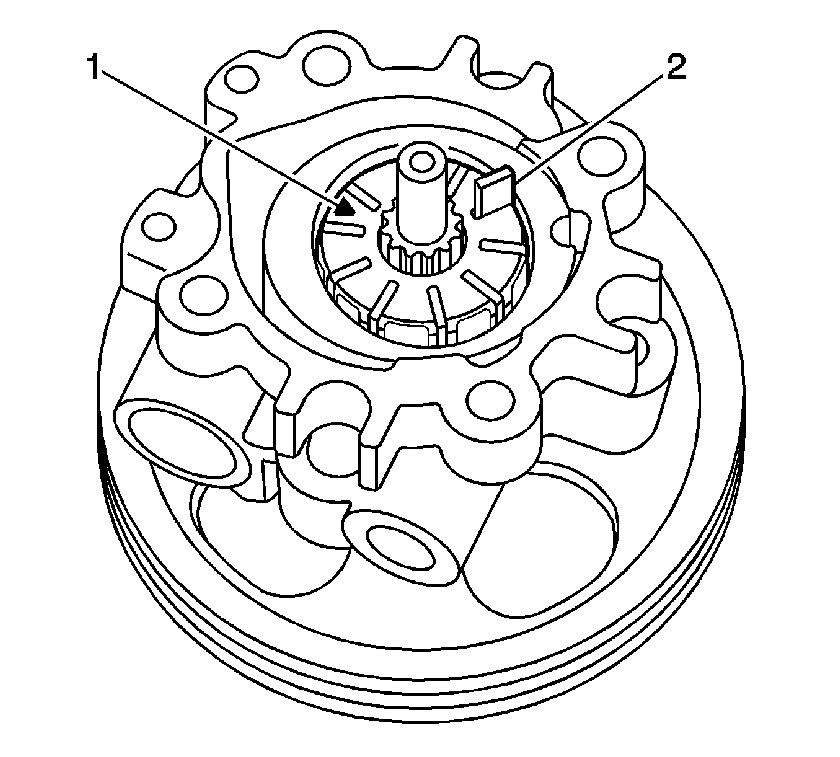
- Remove the pump vanes (2) and the pump rotor (1).
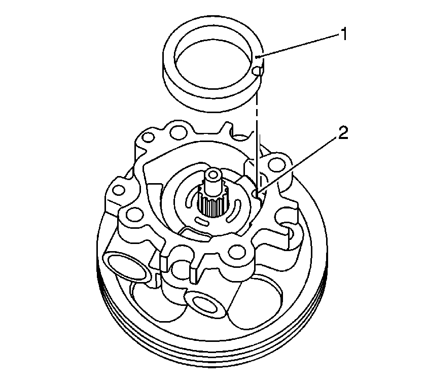
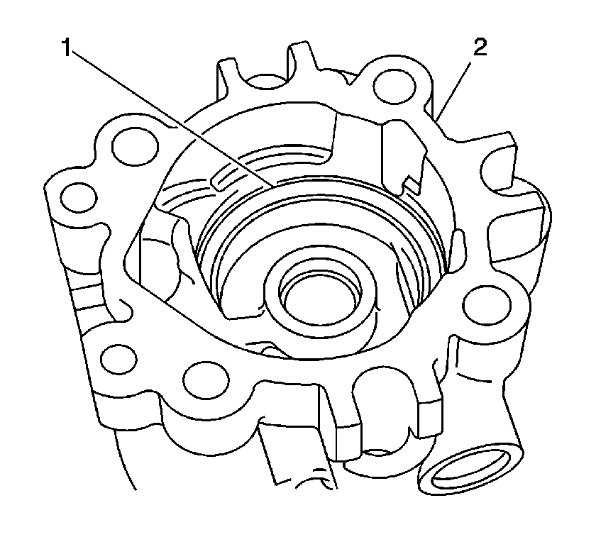
- Remove the pump ring (1).
- Remove the pulley and the pump shaft from the front housing.
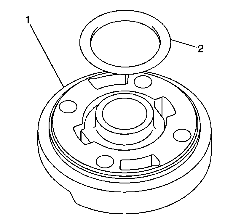
- Remove the pump plate (1).
- Remove the small plate seal (2).
- Remove the large plate seal (1).
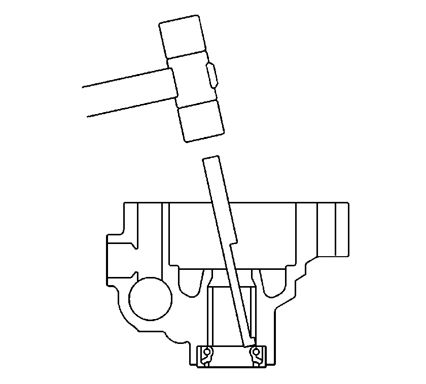
- Remove the pump shaft seal from the front housing.
Inspection Procedure
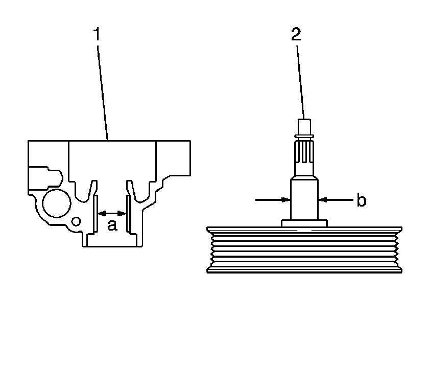
- Measure the outside diameter (b) of the pump shaft (2).
- Measure the inside diameter (a) of the pump shaft hole in the front housing (1).
- Calculate the clearance for the pump shaft seal. If the clearance is not within the specifications, replace the power steering pump.
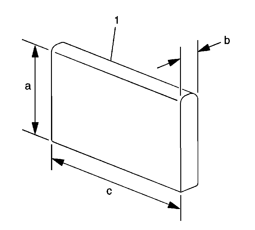
- Measure the height (a) of each vane (1).
- Measure the length (c) of each vane.
- Measure the thickness (b) of each vane.
- Use a feeler gage in order to measure the clearance between each vane and the corresponding slot in the rotor. If the dimensions of the rotor or the vanes are not within the specifications, replace the pump.
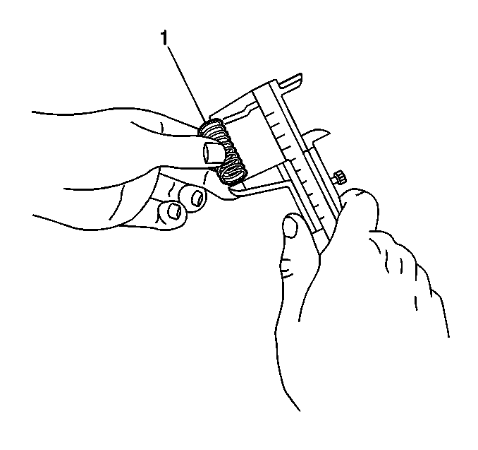
- Measure the free length of the flow control valve spring (1). If the free length of the spring is not within the specification, replace the pump.
- Complete the following steps in order to test the flow control valve:
- Inspect the pump inlet tube and the front housing. If the pump inlet tube does not seal properly against the front housing, replace the pump.
- If the pump components meet the specifications, assemble the pump. Refer to Power Steering Pump Assemble . If the pump components do not meet the specifications, replace the pump. Refer to Power Steering Pump Replacement .
Specification
The minimum clearance for the pump shaft seal is 0.021 mm (0.0008 in). The maximum clearance for the pump shaft seal is 0.070 mm (0.0028 in).
Specification
The minimum height of each vane is 7.60 mm (0.299 in).
Specification
The minimum length of each vane is 11.993 mm (0.4722 in).
Specification
The minimum thickness of each vane is 1.405 mm (0.0553 in).
Specification
The maximum clearance between a vane and the rotor is 0.030 mm (0.0012 in).
Specification
The minimum free length of the spring is 36.9 mm (1.45 in).
| 9.1. | Use your finger in order to plug 1 hole on the side of the valve. |
| 9.2. | Apply compressed air, 392-490 kPa (57-71 psi) to the other hole on the side of the valve. |
| 9.3. | If air exits the hole in the bottom end of the valve, replace the valve. |
| 9.4. | Apply fluid to the valve. Refer to Fluid and Lubricant Recommendations . |
| 9.5. | Apply fluid to the flow control valve hole in the front housing. |
| 9.6. | Hold the pump front housing in a position in order to insert the valve vertically into the housing. |
| 9.7. | Insert the valve into the front housing. If the valve does not slide smoothly into the front housing, replace the pump. |
